Method for producing forging die, forging die and forged article

a technology of forging dies and forged objects, applied in the direction of manufacturing tools, cutting tools, forging/hammering/pressing machines, etc., can solve the problems of increasing tool replacement frequency, affecting productivity, and unable to realize highly efficient processing, so as to ensure tool life, ensure high-speed cutting, and achieve easy determination of optimal working conditions

Inactive Publication Date: 2011-04-26
SHOWA DENKO KK
View PDF28 Cites 6 Cited by
  • Summary
  • Abstract
  • Description
  • Claims
  • Application Information

AI Technical Summary

Benefits of technology

[0022]According to the present invention, a direct cutting method is employed for producing a forging die, in which a die material is cut under specific conditions under which the length of tool extension, radius of the cutting edge of the ball end mill, spindle speed and feed rate satisfy a predetermined relation. Therefore, optimal working conditions can be easily determined, and high-speed cutting can be realized. Moreover, tool life is ensured, polishing can be eliminated, and thus the invention method enables highly efficient production of a forging die as a whole.

Problems solved by technology

However, tool life becomes shortened, resulting in increased tool costs.
Another problem with the shortened tool life is that increased frequency of tool replacement adversely affects productivity.
Thus, realization of highly efficient processing still encounters difficulty.
However, according to the technique described in Patent Document 1, the requirements of 75% or higher CBN sintered material accounting the entire material of the tool and a cutting speed of 1,500 m / min or more are very special conditions which cannot be fulfilled by generally employed machine tools, and in addition, the suggested tool is quite expensive and impractical.
Patent Document 2 discloses investigations on the material, but fails to discuss processing conditions so as to identify specific, optimal conditions.
However, it fails to disclose specific conditions of the cutting process.
Under conventional situations where spindle speed and feed rate are determined on a trial and error basis, when the length of tool extension is increased, optimal conditions cannot be obtained.
For example, in usual practice where a spindle speed is set to a maximum possible level, and the feed and the depth of cut (pitch) are calculated on the basis of the required surface roughness, if the calculated feed and depth of cut values are employed as they are, undesirable phenomena, such as chatter of the tool, are caused.
In such a case, undesirable phenomena actually occur and correction of the values is needed.
In reality, in order to determine the conditions under which the best finished surface can be obtained, iterations of trials and errors have been needed, which is time-consuming.
In addition, when a die is produced through conventional direct cutting at high cutting speed, the finish is poor, and therefore, a polishing step is indispensable.
The polishing step requires a considerable workload, increasing the die production cost and extending the production time.
Moreover, polishing has been a major cause of defects, as it is generally performed by hand.

Method used


Image

  • Method for producing forging die, forging die and forged article
  • Method for producing forging die, forging die and forged article
  • Method for producing forging die, forging die and forged article

Examples


examples

[0098]The present invention will next be described in detail by way of examples, which should not be construed as limiting the invention thereto.

[0099]The die material employed is SKD 61 having HRC hardness of 48±2. The tool employed is a ball end mill of R0.5 to R2. The surface coating is CrSiN. Other conditions are shown in Tables 1 and 2.

[0100]The surface finish conditions after the material underwent cutting were observed under a magnifying lens and evaluated. The results of evaluation are shown in Table 1. Table 2 shows results of comparison between a conventional method and the present invention.

[0101]

TABLE 1TOOLLENGTH OF TOOLROTATIONFEEDRADIUSEXTENSION(A)(B)(B / A)2 ×SURFACE ROUGHNESSSAMPLE NO.(R) (mm)(L) (mm)L / 2R(rpm)(mm / MIN)(B / A)(L / 2R)CONDITIONSCOMP. EX. 12153.752000036000.1800.122xINSERTION MARKSEX. 12153.752000020000.1000.038∘EX. 22153.752000012000.0600.014∘COMP. EX. 22153.75200009000.0450.008xSCRATCH MARKSCOMP. EX. 32153.75200007000.0350.005xSCRATCH MARKSCOMP. EX. 42153.75...


PUM

PropertyMeasurementUnit
surface roughness Rmaxaaaaaaaaaa
angleaaaaaaaaaa
tool radiusaaaaaaaaaa

Abstract

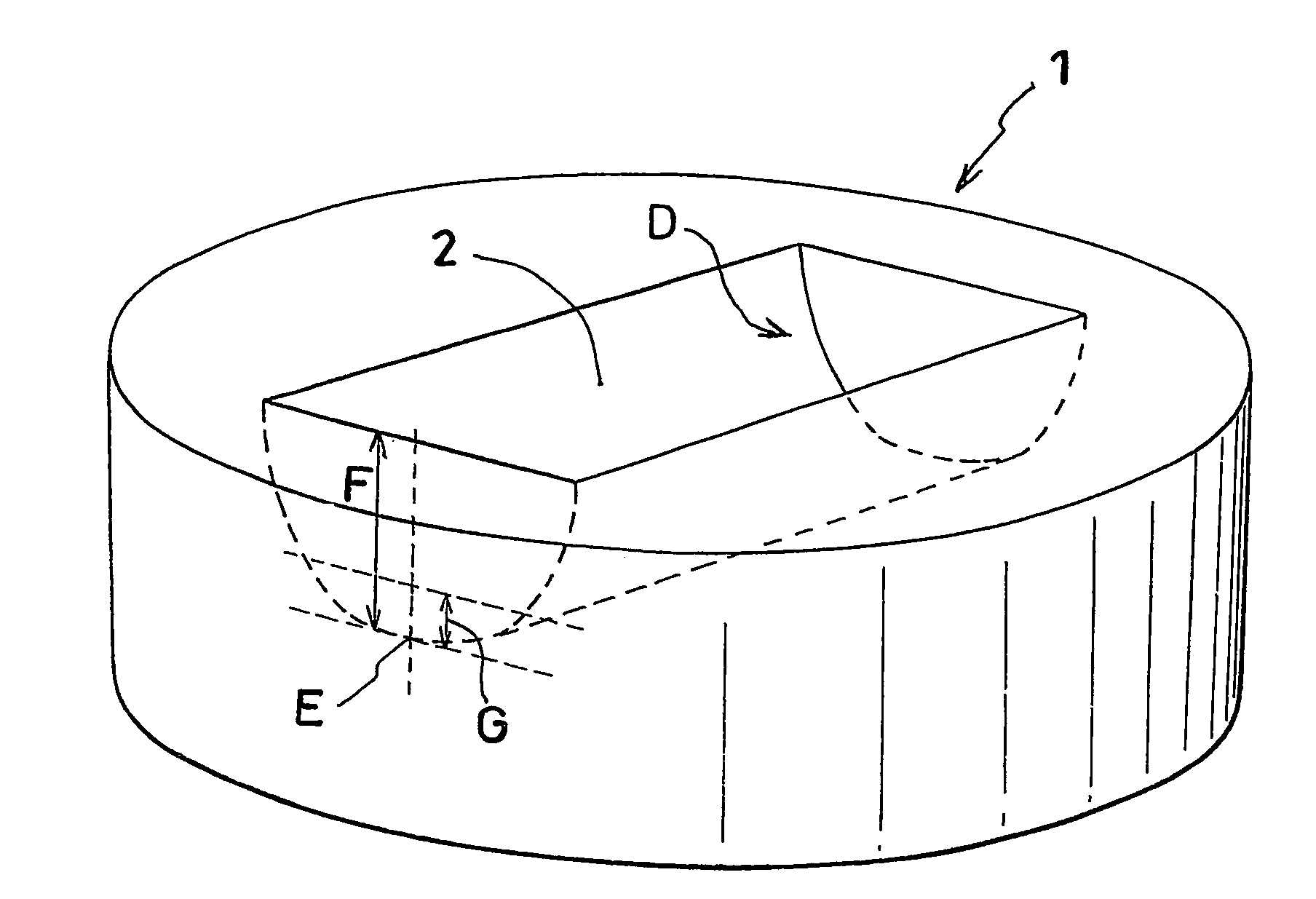
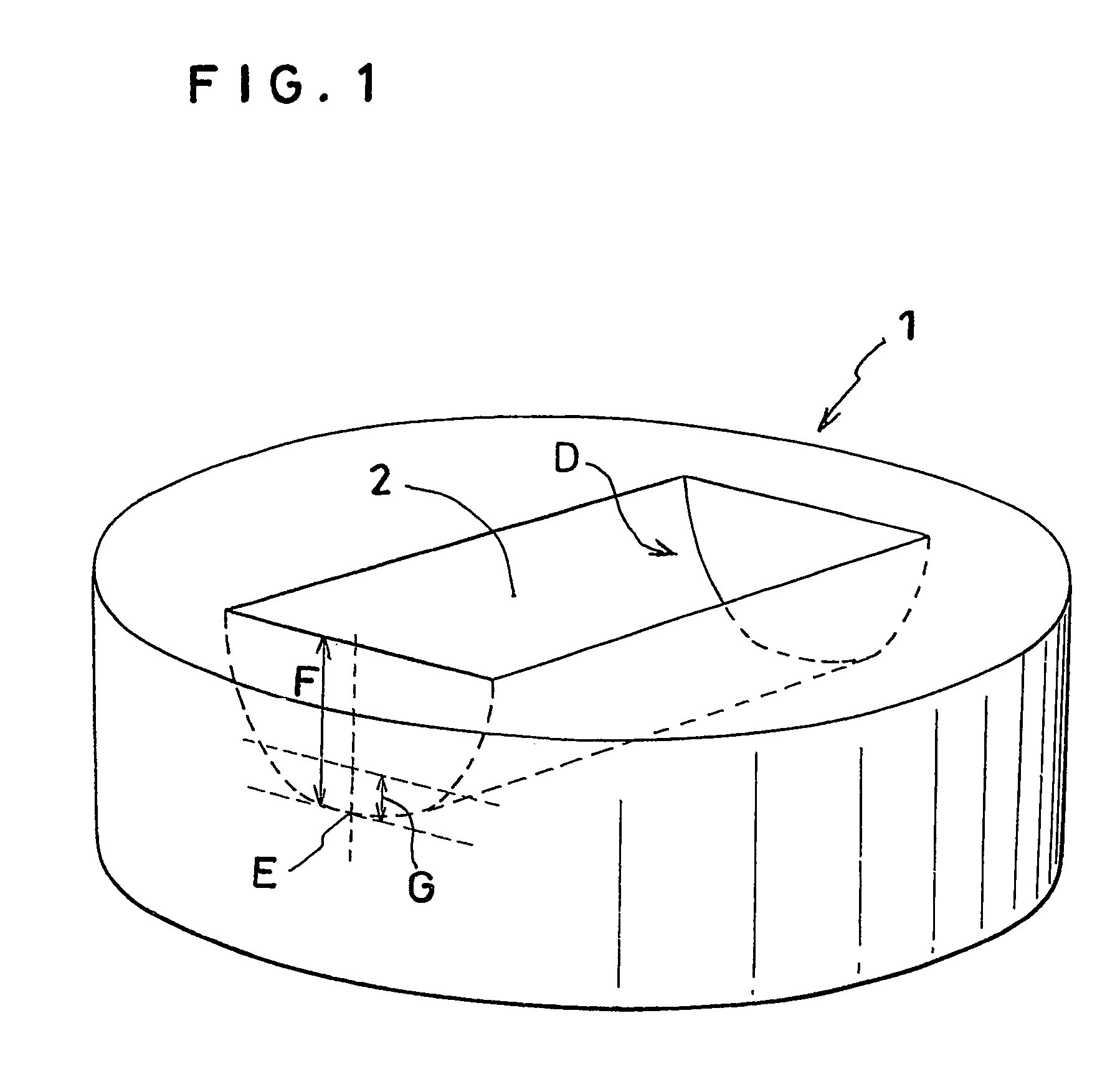
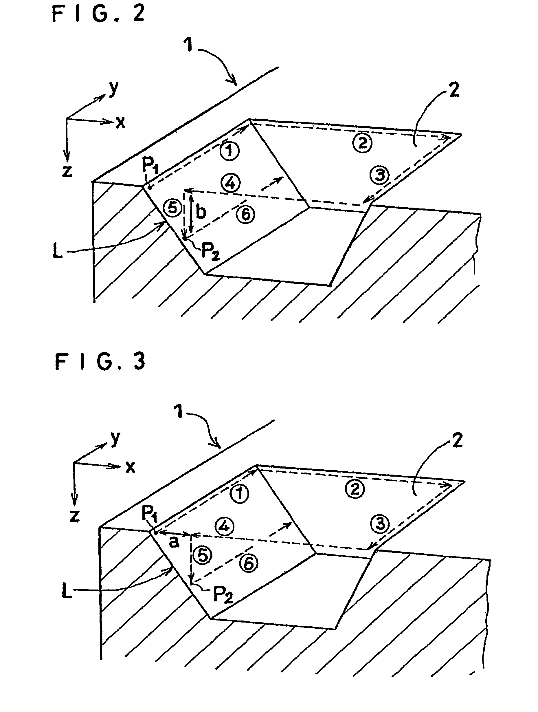
A forging die production method comprising a cutting step which employs, as a cutting tool, a ball end mill having a surface which has undergone a hardening treatment and in which a forging die material is cut under conditions where a length of tool extension L (mm), radius R (mm) of a cutting edge of the ball end mill, spindle speed A (rpm) and feed rate B (mm / min) satisfy (B / A)2×(L / (2×R))=0.01 to 0.05. A forging die is produced through the forging die production method. A forged article is produced through forging by use of the produced forging die.

Description

CROSS REFERENCE TO RELATED APPLICATIONS[0001]This application is an application filed under 35 U.S.C. §111(a) claiming the benefit pursuant to 35 U.S.C. §119(e)(1) of the filing date of Provisional Application No. 60 / 534,098 filed Jan. 5, 2004 pursuant to 35 U.S.C. §111(b).TECHNICAL FIELD[0002]The present invention relates to a method for producing a forging die for producing a forging die through use of an aluminum alloy as a raw material; to a forging die; and to forged articles obtained by forging with the forging die.BACKGROUND ART[0003]Cutting processes involve three fundamental factors: high accuracy, high efficiency, and low cost. Of the three factors, high efficiency is considered to be attained by increasing cutting speed, and therefore, means for such increase has become of interest. With an improvement in cutting speed, cutting efficiency also improves. However, tool life becomes shortened, resulting in increased tool costs. Another problem with the shortened tool life is...

Claims


Application Information

Patent Timeline
Patent Type & Authority Patents(United States)
IPC IPC(8): B23C3/00B23C5/10B21J13/02B21K5/20B23C3/20B23P15/24
CPCB21J13/02B21K5/20B23C5/1009B23P15/24B23C3/20Y10T409/303808B23C5/20
Inventor ASAKAWA, JUN
Owner SHOWA DENKO KK
Why Eureka
Try Eureka