Gas discharge tube

a gas discharge tube and gas discharge technology, applied in gas-filled discharge tubes, electric discharge lamps, solid cathodes, etc., can solve the problems of not meeting the requirements of modern discharge devices, unable to determine spark voltage, reproducing, etc., and achieves less volume, less weight, and less consumption of raw materials.

Active Publication Date: 2011-04-26
BOURNS INC
View PDF11 Cites 11 Cited by
  • Summary
  • Abstract
  • Description
  • Claims
  • Application Information

AI Technical Summary

Benefits of technology

[0016]The object of the present invention is to make available gas discharge tubes for all relevant areas of application, said gas discharge tubes exhibiting in particular smaller dimensions compared to other gas discharge tubes showing the same efficiency with less volume, less weight and / or less consumption of raw materials.
[0023]For some electric utilities polymer composite materials have been used for some types of insulators which consist of a central rod made of fibre reinforced plastic and an outer weathershed made of silicone rubber or EPDM. Composite insulators are less costly, lighter weight, and they have excellent hydrophobic capability. This combination makes them ideal for service in polluted areas. However, these materials do not yet have the long-term proven service life of glass and porcelain.

Problems solved by technology

These are, however, not comparable to the modern surge arresters with respect to size, reliability, performance and production technology.
Thus the formation of the spark is, to a great part, based on the underlying material, which is not necessarily inert, but is due to oxidation in the existing environment, which means that the spark voltage can not be determined, and reproduced.
Such a device does not meet the requirements of modern discharge devices.
It is obvious, that this solution has specific drawbacks associated inter alia with the radioactivity and / or toxicity of the components.

Method used


Image

  • Gas discharge tube
  • Gas discharge tube
  • Gas discharge tube

Examples


production example

[0060]A surge arrester was produced by subjecting a batch of copper electrodes to the following treatment steps: first, the electrodes were rinsed in a solvent, removing loose contamination and traces of grease or fat. The electrodes and insulating rings were subject to vacuum, filled with a certain gas or a gas mix to a certain pressure and soldered to provide gas discharge tubes.

[0061]In case the electrodes are to be provided with a coating the electrodes are placed in a mask, exposing the area to be coated. A set of electrodes, cleaned and placed in a mask, were then introduced in a sputtering chamber, which was evacuated. The electrodes were then subjected to cleaning by reverse sputtering, removing impurities from the electrodes. The current was then reversed and methane led into the chamber. By supplying chromium in the form of chromium cathodes, a process of reactive sputtering was performed. The electrodes received a layer of graphite with an addition of chromium atoms locki...


PUM


Abstract

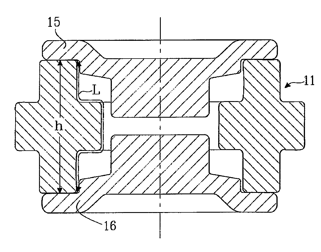
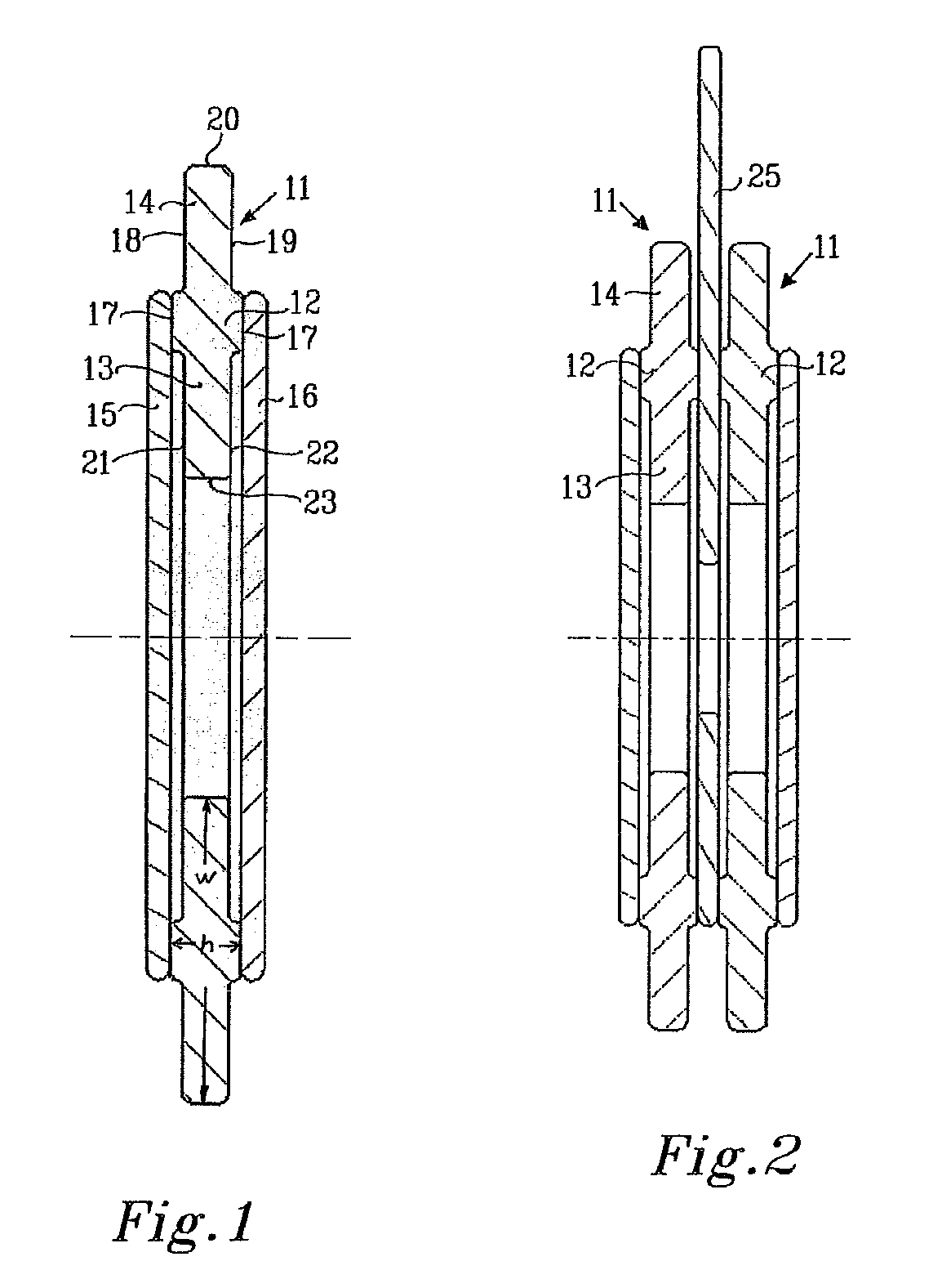
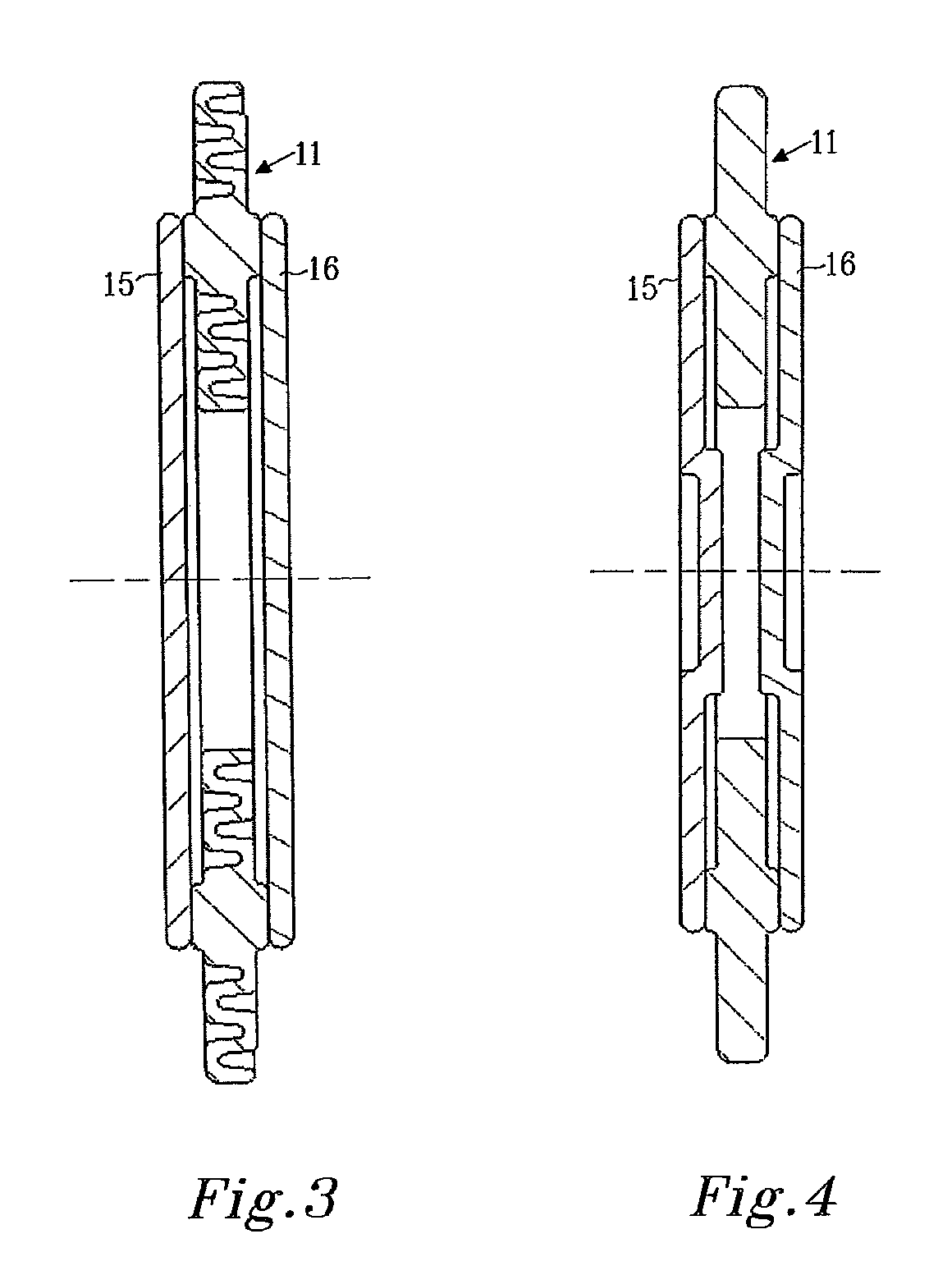
A new gas discharge tube comprising at least two electrodes and at least one hollow insulator ring fastened to at least one of the electrodes, wherein the insulating ring has an extended length for a creeping current on at least one of the surfaces inside and / or outside compared to its height thereby providing a long distance to any possible creeping current.

Description

PRIORITY INFORMATION[0001]The present application claims priority to Swedish Application No. 0701246-1, filed on May 22, 2007, which is incorporated herein by reference in its entirety.DESCRIPTION[0002]1. Technical Field[0003]The present invention concerns the field of gas discharge tubes including surge arresters, gas arresters, high-intensity discharge tubes, spark gaps, switching spark gaps and triggered spark gaps, used in various applications, such as surge voltage protectors for communications networks voltage controlled switching of capacitive discharge circuits and in particular to a new type of such devices which exhibit higher selectivity, better performance and are more environmentally friendly. In particular the present invention relates to the design of an insulating part of such a gas discharge tube.[0004]2. Background of the Invention[0005]When electronic equipment is connected to long signal or power lines, antenna etc, it is exposed to transients generated by induct...

Claims


Application Information

Patent Timeline
Patent Type & Authority Patents(United States)
IPC IPC(8): H01J11/00
CPCH01T4/12
Inventor SCHLEIMANN-JENSEN, JOHANNILSSON, JAN-AKESCHLEIMANN-JENSEN, ARNE
Owner BOURNS INC
Why Eureka
Try Eureka