Brake structure for wheel rotating device

a technology of rotating device and brake structure, which is applied in the direction of braking discs, electric propulsion mounting, transportation and packaging, etc., can solve the problems of difficult layout of brake hoses, inability to increase the torque of motors, and difficulty in increasing the diameter of motors, so as to reduce the size of the brake structure and reduce the size of the braking mechanism. , the effect of less dragging

Inactive Publication Date: 2011-05-10
HONDA MOTOR CO LTD
View PDF17 Cites 28 Cited by
  • Summary
  • Abstract
  • Description
  • Claims
  • Application Information

AI Technical Summary

Benefits of technology

[0008]With this configuration of the brake structure, brake fluid is supplied from the brake fluid passage via the brake fluid supply port and into the housing, to thereby generate pressing force at the pressing force generating unit. This makes it possible to press the frictional members against the brake rotor to brake the wheel.
[0022]According to the present invention, it is possible to reduce the size of the braking mechanism including the fluid passage (i.e., brake fluid passage) for brake application. Therefore, the diameter of the motor can be extended to increase the motor torque.

Problems solved by technology

This makes it difficult to increase the diameter of the motor, and as a result, torque of the motor cannot be increased.
Further, it is difficult to layout the brake hose.

Method used


Image

  • Brake structure for wheel rotating device
  • Brake structure for wheel rotating device
  • Brake structure for wheel rotating device

Examples


first embodiment

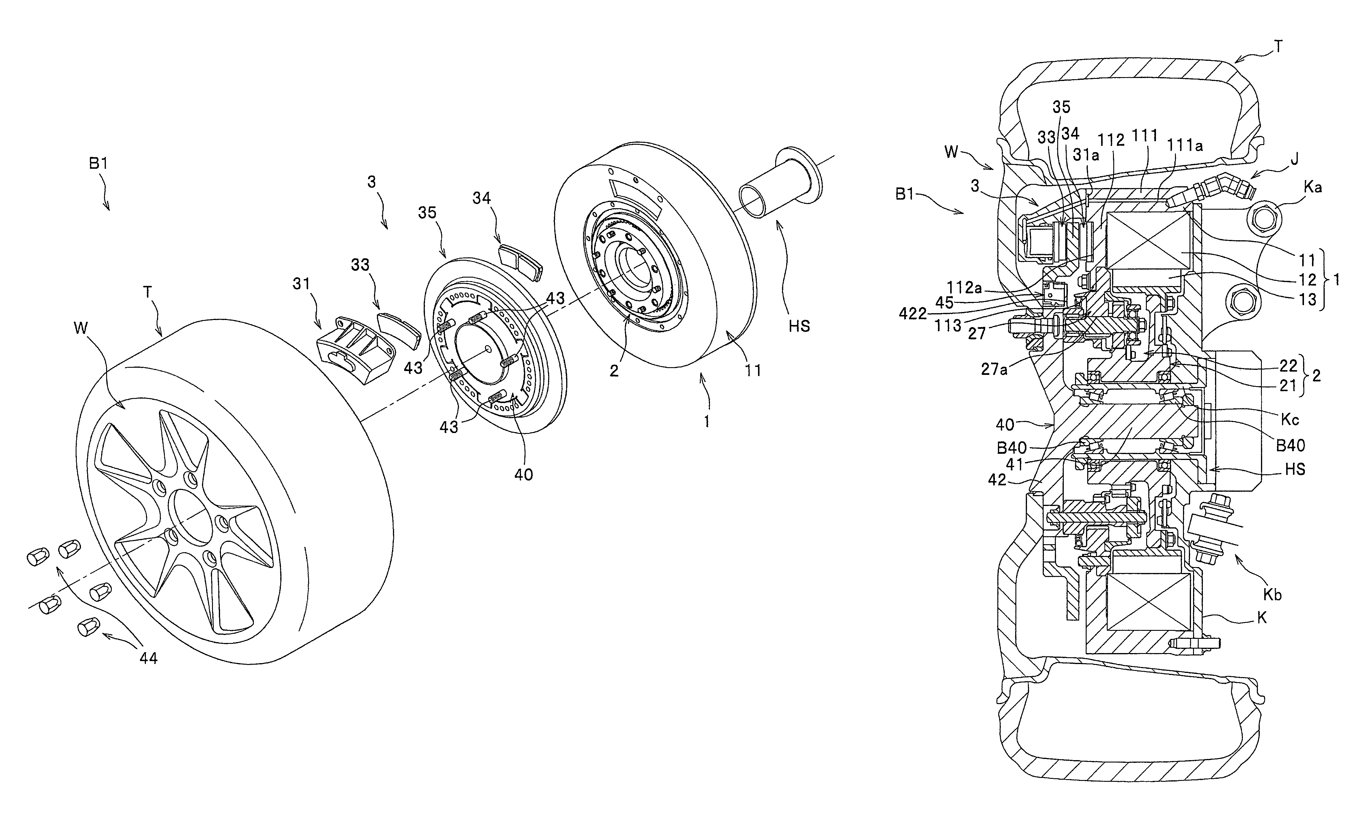
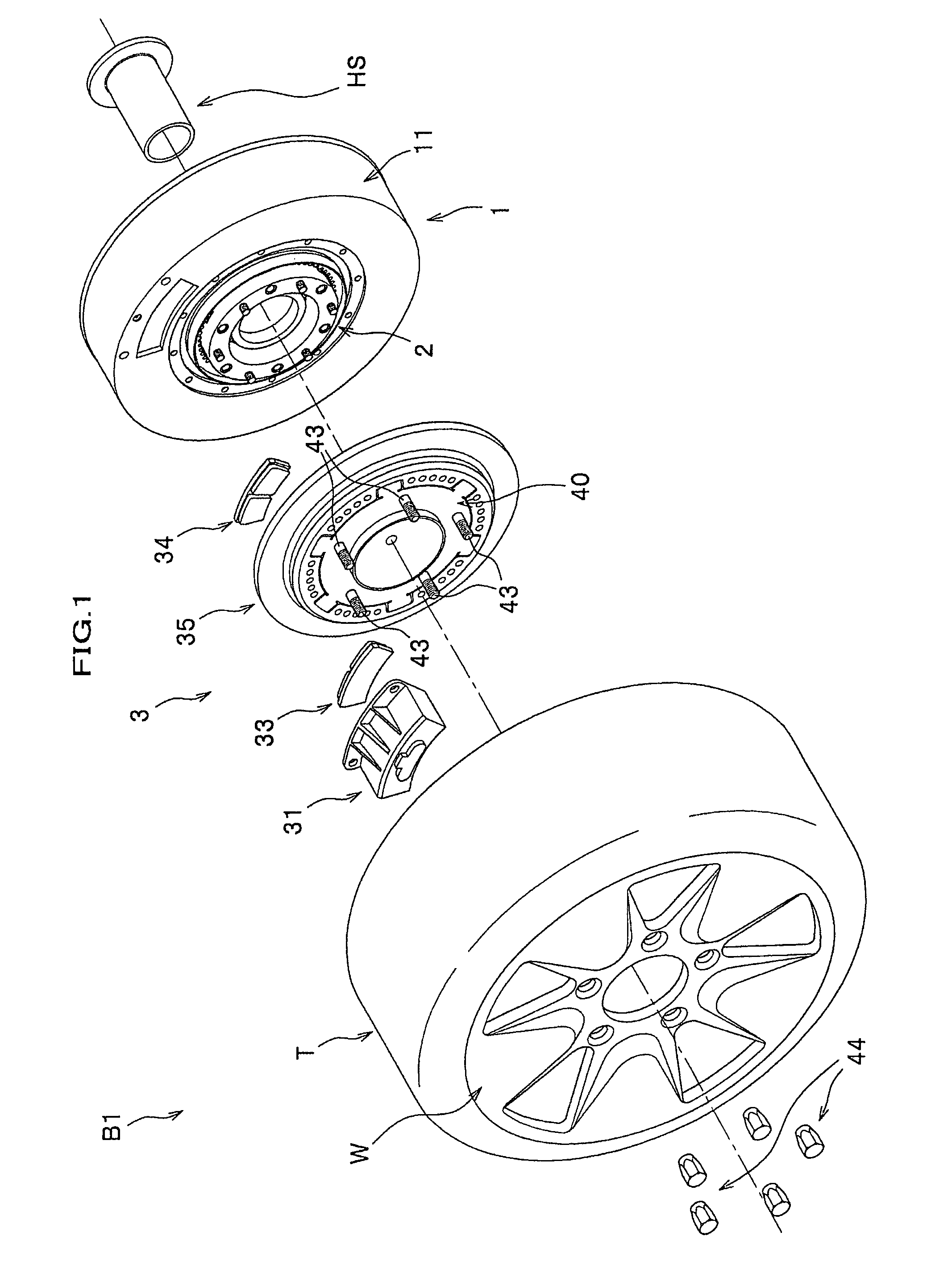
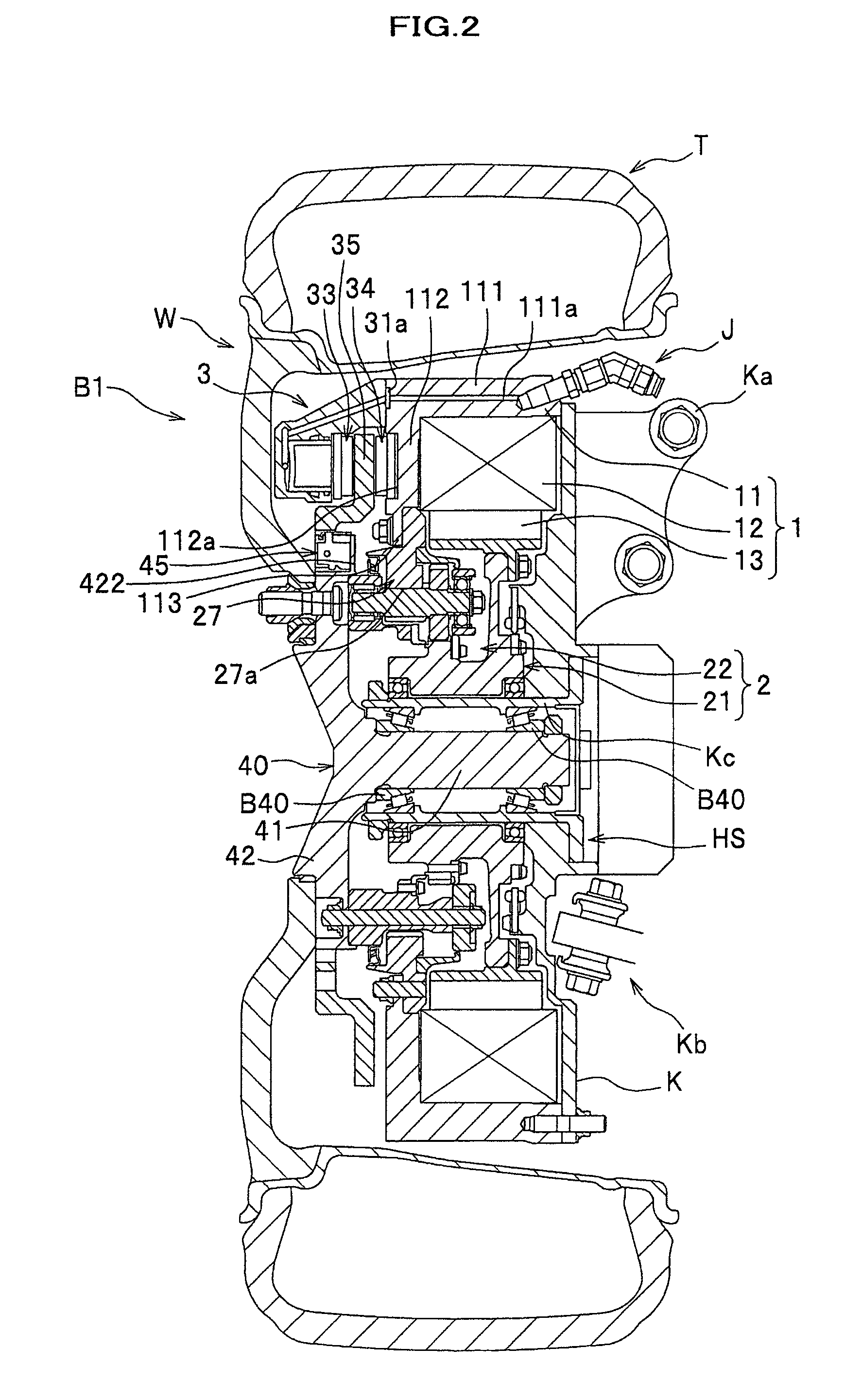
[0042]A brake structure for a wheel rotating device according to a first embodiment will be described below. In this preferred embodiment, explanation will be given on the case in which a brake structure according to the present invention is adapted to a disk brake. The brake structure for the wheel rotating device can be adapted to any of the wheels including front right, front left, rear right, and rear left wheels. In this preferred embodiment, the brake structure will be explained as an example where it is adapted to the front left wheel.

[0043]As shown in FIG. 1, the brake structure for the wheel rotating device (hereinafter referred to as the brake structure B1) is provided inside the wheel W and equipped with a motor (in-wheel motor) 1 for generating a rotation force for rotating the wheel W, reduction gears 2 (see FIG. 2) for increasing the motor torque while reducing the rotation speed of the motor 1 and then transmitting the rotation force to the wheel W, and a braking mech...

second embodiment

[0092]A brake structure for a wheel rotating device according to a second embodiment will be described below. In this preferred embodiment, an explanation will be given on the case in which a brake structure according to the present invention is adapted to a drum brake. The brake structure for the wheel rotating device can be adapted to any of the wheels including front right, front left, rear right, and rear left wheels. In this preferred embodiment, the brake structure will be explained as an example where it is adapted to the front left wheel.

[0093]As shown in FIG. 12, the brake structure for the wheel rotating device (hereinafter referred to as the brake structure B2) is provided inside the wheel W, to which a tire T is mounted on the rim. The brake structure is equipped with a motor (in-wheel motor) 1 for generating a rotation force for rotating the wheel W, reduction gears 2 (see FIG. 13) for increasing the motor torque while reducing the rotation speed of the motor 1 and then...


PUM


Abstract

A brake structure for a wheel rotating device is disclosed, which comprises a motor provided in a wheel and is driven for rotating the wheel, and a braking mechanism for actuating brake to brake the wheel. The motor includes: a motor housing; a stator positioned in and fixed to the motor housing; and a rotor positioned in the motor housing and facing to the stator. The braking mechanism includes: a brake rotor to rotate with the wheel; frictional members to be in contact with the brake rotor for generation of braking force; a pressing force generating unit for generating pressing force of the frictional members so that the frictional members are urged to and pressed against the brake rotor by supplying brake fluid through a brake fluid passage to transmit fluid pressure; and a housing for the pressing force generating unit. The brake fluid passage is formed inside a wall of the motor housing, and is connected to a brake fluid supply port provided in the housing for the pressing force generating unit.

Description

CROSS REFERENCE TO RELATED APPLICATIONS[0001]This application claims the foreign priority benefit under Title 35, United States Code, §119(a)-(d) of Japanese Patent Application No. 2006-231500 filed on Aug. 29, 2006 in the Japan Patent Office, the disclosure of which is herein incorporated by reference in its entirety.BACKGROUND OF THE INVENTION[0002]The present invention relates to a wheel rotating device for rotating a wheel of an automobile, and more particularly to a brake structure for a wheel rotating device which can reduce the size of the structure.[0003]In-wheel motor for driving a wheel of an automobile is arranged in a limited space of the wheel. In recent years, attempts have been made to design layout of various parts so that the size of the whole device can be reduced while increasing the diameter of the motor for improving motor torque. For example, Japanese Laid-open Patent Application No. 2004-114858 discloses such a layout design. As a brake structure for the wheel...

Claims


Application Information

Patent Timeline
Patent Type & Authority Patents(United States)
IPC IPC(8): B60K1/00F16D55/00F16D65/18F16D65/22
CPCB60K7/0007F16D51/18F16D55/22F16D65/12F16D51/20B60K17/046B60K2007/0038B60K2007/0092F16D2121/02F16D2051/003F16D2065/1368F16D2065/1396
Inventor YOSHINO, TSUTOMUOKU, KOICHI
Owner HONDA MOTOR CO LTD
Why Eureka
Try Eureka