Fiber amplifiers and fiber lasers with reduced out-of-band gain

a fiber laser and fiber amplifier technology, applied in the field of optical amplifiers and lasers, can solve the problem of limiting the gain available at the wavelength of interest, and achieve the effect of a wider range of application

Inactive Publication Date: 2011-05-10
ELECTRO SCI IND INC
View PDF6 Cites 11 Cited by
  • Summary
  • Abstract
  • Description
  • Claims
  • Application Information

AI Technical Summary

Benefits of technology

[0018]According to another specific embodiment of the present invention, an optical amplifier is provided. The amplifier includes a length of rare-earth-doped fiber to amplify optical pulse signal at a first wavelength. The optical signal wavelength is located outside of a gain peak of the rare-earth-doped fiber. The amplifier also includes an optical pump light at a second wavelength, which is injected into the length of rare-earth-doped fiber. The pump light wavelength is located nearby of a gain peak of the rare-earth-doped fiber, such that the amplified spontaneous emission and the gain at the peak are substantially reduced.
[0019]According to yet another specific embodiment of the present invention, an optical amplifier is provided. The amplifier includes a length of rare-earth-doped fiber to amplify optical pulse signal at a first wavelength. The optical signal wavelength is located outside of a gain peak of the rare-earth-doped fiber. The amplifier also includes and optical seed light at a second wavelength, which is injected into the length of rare-earth-doped fiber. The seed light wavelength is located nearby of a gain peak of the rare-earth-doped fiber. The optical amplifier further includes an optical pump light at a third wavelength, which is also injected into the length of rare-earth-doped fiber. The pump light wavelength is chosen such that a substantial portion of the pump light is converted to light at the seed wavelength, and such that the amplified spontaneous emission and the gain at the peak are substantially reduced.

Problems solved by technology

Such ASE or lasing will limit the amount of gain available at the wavelength of interest.
In some amplifier applications, large out-of-band ASE will limit the available gain and the ASE power may be larger than the signal power at the wavelength of interest.

Method used


Image

  • Fiber amplifiers and fiber lasers with reduced out-of-band gain
  • Fiber amplifiers and fiber lasers with reduced out-of-band gain
  • Fiber amplifiers and fiber lasers with reduced out-of-band gain

Examples


Embodiment Construction

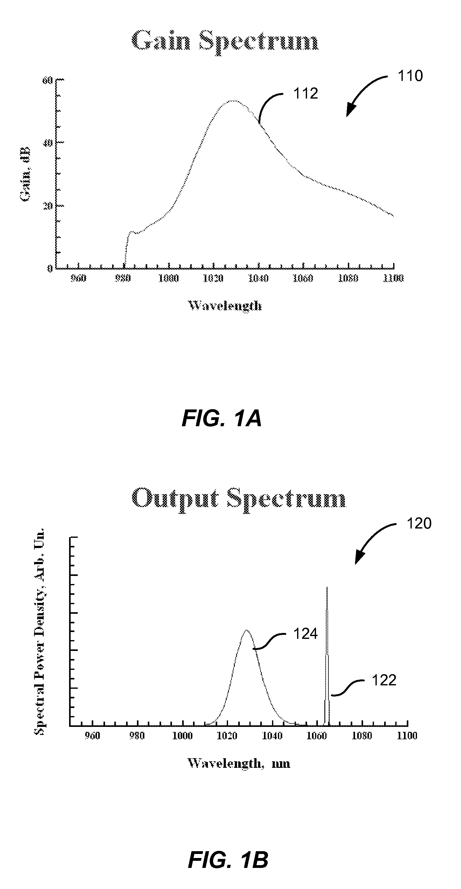
[0037]FIG. 1A is a simplified illustration of spectral gain in an ytterbium-doped amplifier optically pumped at 976 nm. To produce the spectral gain curve 110 illustrated in FIG. 1A, an ytterbium-doped optical fiber was core-pumped at a wavelength of 976 nm with 500 mW of pump power. The length of optical fiber was selected to achieve close to 30 dB of gain at 1064 nm. To generate the spectral gain data presented in FIG. 1A, the inversion of the active material was about 47%. A significant portion of the pump light is absorbed during pumping of the ytterbium amplifier.

[0038]Referring to FIG. 1A, a substantial gain peak 112 is present in the spectral gain curve at a wavelength of about 1030 nm. For applications in which either lasing or amplification at a wavelength of 1064 nm is desired, the gain peak 112 at about 1030 nm represents out-of-band gain. In the example illustrated in FIG. 1A, the gain peak 112 is over 50 dB. It will be appreciated that the high value of gain peak 112 ma...


PUM


Abstract

A method of operating a fiber amplifier characterized by a spectral gain curve includes providing an input signal at a signal wavelength. The signal wavelength lies within an in-band portion of the spectral gain curve extending from a first in-band wavelength to a second in-band wavelength, the in-band portion being characterized by a first amplitude range. The method also includes providing pump radiation at a pump wavelength. The pump wavelength is less than the signal wavelength. The method further includes coupling the pump radiation to the fiber amplifier and amplifying the input signal to generate an output signal. All portions of the spectral gain curve at wavelengths less than the first in-band wavelength and greater than the pump wavelength are characterized by a second amplitude less than or equal to 10 dB greater than the first amplitude range.

Description

CROSS-REFERENCES TO RELATED APPLICATIONS[0001]The present application claims benefit under 35 U.S.C. §119(e) of U.S. Provisional Patent Application No. 60 / 836,244, filed Aug. 7, 2006, entitled “Fiber amplifiers and fiber lasers with reduced out-of-band gain,” the disclosure of which is incorporated herein by reference in its entirety.BACKGROUND OF THE INVENTION[0002]The present invention relates generally to the field of optical amplifiers and lasers. More particularly, the present invention relates to methods and systems related to optically excited rare-earth doped optical fiber gain medium. Merely by way of example, the methods and systems have been applied to reducing out-of-band gain and amplified spontaneous emission in optical fibers. But it would be recognized that the invention has a much broader range of applicability.[0003]Conventional laser-based material processing has generally used high peak power pulsed lasers, for example, Q-switched Nd:YAG lasers operating at 1064 ...

Claims


Application Information

Patent Timeline
Patent Type & Authority Patents(United States)
IPC IPC(8): H01S3/00
CPCH01S3/06754H01S3/14H01S3/2375H01S3/09415H01S2301/04H01S3/1618H01S3/067H01S3/0941H04B10/291
Inventor MURISON, RICHARDPANARELLO, TULLIOREID, BENOITBOULA-PICARD, REYNALD
Owner ELECTRO SCI IND INC
Why Eureka
Try Eureka