Plasma resistant seal

a technology of plasma and sealing shell, applied in the direction of sealing, transportation and packaging, other chemical processes, etc., can solve the problems of lowering the function and poor sealing performance against atmospheric pressure, and achieve the effect of improving the plasma resisting performan

Inactive Publication Date: 2011-05-17
NOK CORP
View PDF19 Cites 11 Cited by
  • Summary
  • Abstract
  • Description
  • Claims
  • Application Information

AI Technical Summary

Benefits of technology

[0014]The seal constituted by a combination of the packing / O-ring and the plasma seal is attached to the installation groove which is previously provided in the installation member, and the plasma seal is attached to the plasma irradiating side of the packing / O-ring for the purpose of protecting the packing / O-ring from the plasma. As a structure of the installation, as described in the third aspect, it is preferable that the plasma seal installation groove which is shallower than the depth of the packing / O-ring installation groove is continuously provided in the plasma irradiation side of the packing / O-ring installation groove arranged in the installation member, the packing / O-ring is attached to the latter packing / O-ring installation groove, and the plasma seal is attached to the former plasma seal installation groove. In accordance with this structure, since the packing / O-ring is engaged with a side wall portion of an inner surface of the packing / O-ring installation groove, and the plasma seal is engaged with a side wall portion of the plasma seal installation groove, it is possible to prevent the packing / O-ring or the plasma seal from being sucked to the vacuum side so as to be moved. Further, the structure of the installation may be made, as described in the fourth aspect, such that the packing / O-ring is attached to the packing / O-ring installation groove provided in the installation member, and the plasma seal is attached to the plasma irradiation side of the same installation groove. In any case, when the plasma seal is compressed between the installation member and the opponent member at a time of the installation, the plasma is further hard to pass through the plasma seal. Accordingly, it is possible to improve a plasma shielding effect achieved by the plasma seal.
[0033](3) In order to improve the plasma resisting performance, a PTFE backup ring is applied to the packing / O-ring. The packing / O-ring functions as a vacuum seal, and the PTFE backup ring functions as a plasma shield.

Problems solved by technology

However, since energy of the plasma is very strong, even the O-ring 51 made of the rubber such as the FFKM, the FKM or the like provided with the resistance characteristic is scraped due to an influence of the plasma as shown in FIG. 8, and is lost in some cases, so that there is a case that a sealing function is lowered.
Further, there is a case that a seal made of a polytetrafluorethylene (PTFE) is employed as a structure having the resistance characteristic against the plasma, in place of the rubber O-ring 51, however, since the PTFE is inferior to the FFKM and the FKM in a performance as an elastic body, a sealing performance against the atmospheric pressure is not so good.

Method used


Image

  • Plasma resistant seal
  • Plasma resistant seal
  • Plasma resistant seal

Examples


first embodiment

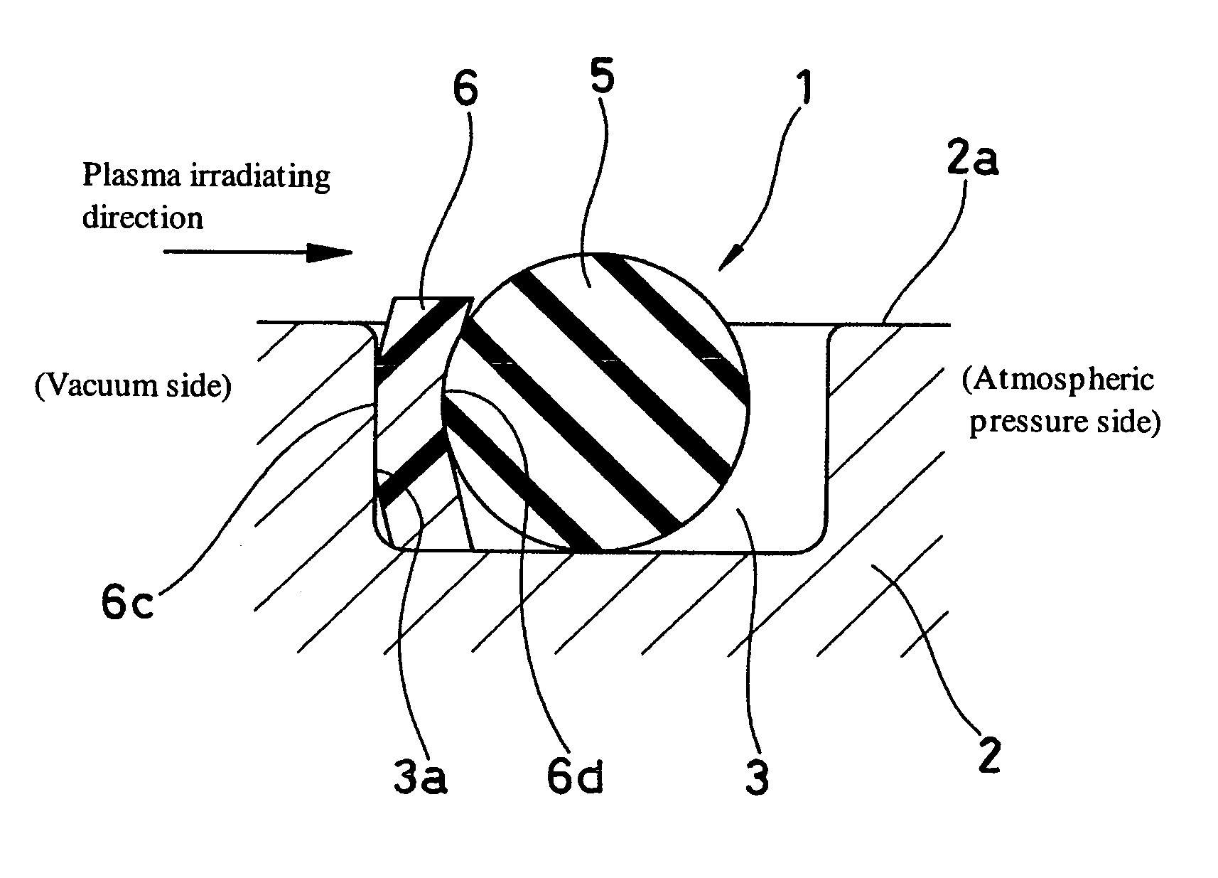
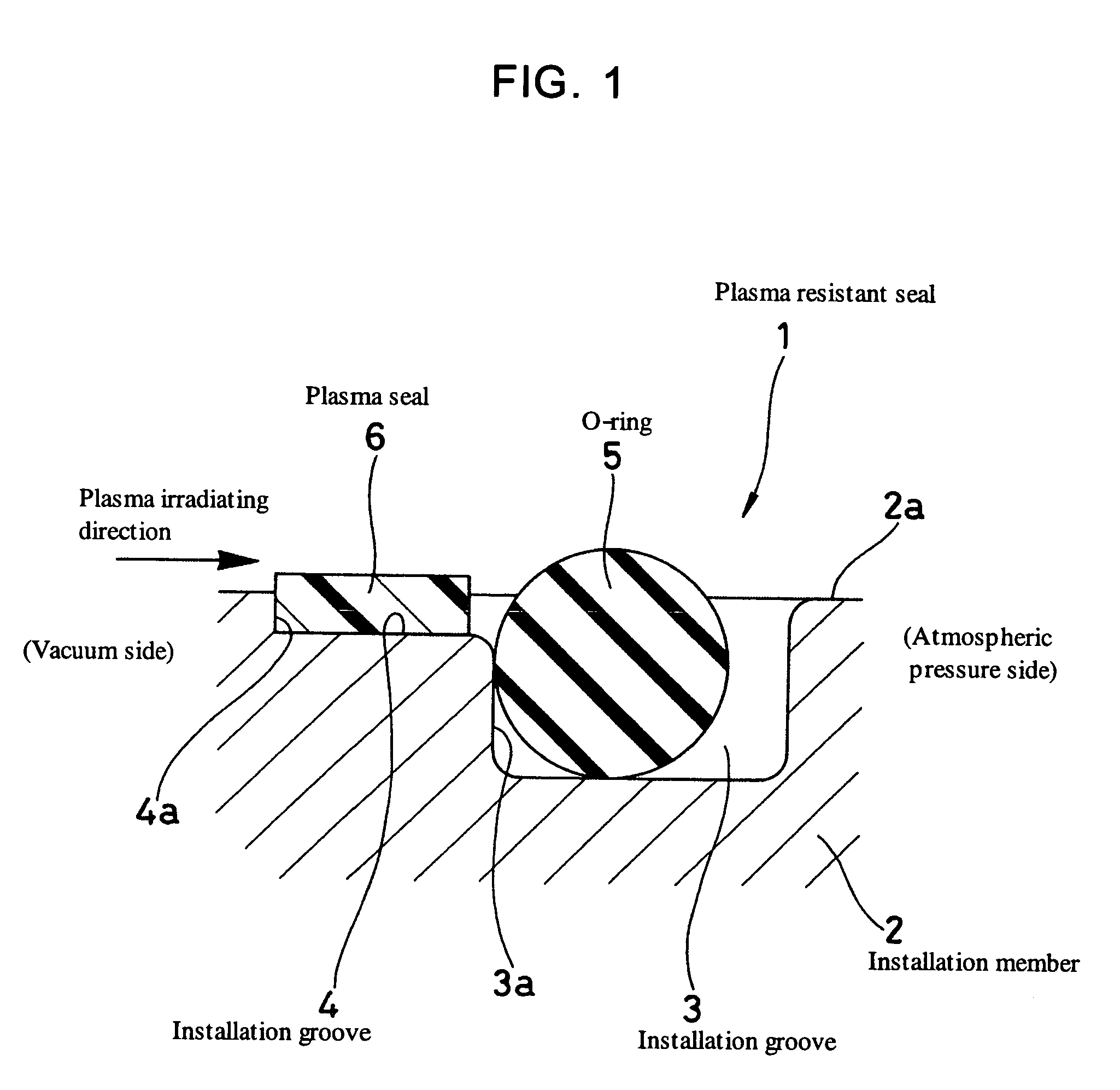
[0043]FIG. 1 shows a cross section of a plasma resistant seal 1 in accordance with a first embodiment of the present invention. The seal 1 in accordance with the embodiment mentioned above is used in a semiconductor manufacturing apparatus, more specifically, an exhaust portion, an intake portion or a chamber portion of a vacuum pump for a semiconductor, or a piping portion or a chamber portion of an etching, ashing or plasma CVD apparatus, and is structured as follows.

[0044]First, an annular O-ring installation groove 3 is provided in an end surface portion 2a of an installation member (a housing in one side) 2 to which the seal 1 is attached, and a plasma seal installation groove 4 which is shallower than a depth of the O-ring installation groove 3 is continuously provided in a plasma irradiating side (an inner diameter side, a left side in the drawing) of the O-ring installation groove 3. Each of the installation grooves 3 and 4 is formed in an approximately quadrangular cross se...

second embodiment

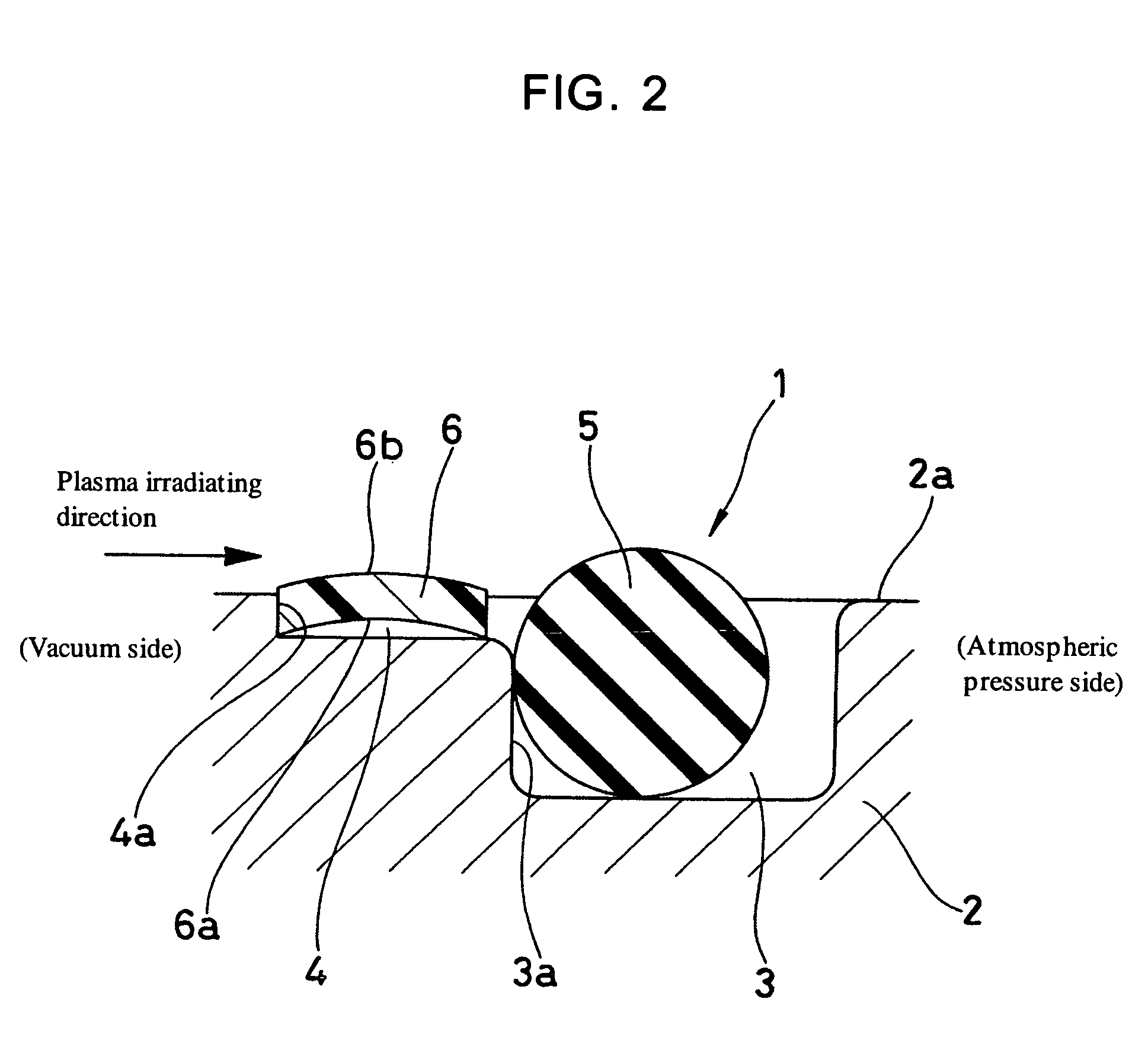
[0058]In the first embodiment mentioned above, the plasma seal 6 is formed in the flat shape and in the rectangular shape long from side to side in the cross section, however, in the case that the plasma seal 6 is formed in a round shell shape in a cross section, it is possible to apply a spring property at an attaching time to the plasma seal 6.

[0059]In other words, as shown in FIG. 2, the plasma seal 6 is formed by a predetermined PTFE, for example, an unfilled type PTFE, and is formed in a round shell shape being long from side to side in the drawing in a cross section, in which a longitudinal direction is arranged along a plasma irradiating direction. The round union end shape means a so-called circular arc shape, and the plasma seal 6 is structured such that a surface in a groove bottom side (a lower surface in the drawing) 6a is formed to be a concave in a circular arc shape in a cross section, and a surface in an opponent member side (an upper surface in the drawing) 6b is fo...

third embodiment

[0061]FIG. 3 shows a cross section of a plasma resistant seal 1 in accordance with a third embodiment of the present invention. The seal 1 in accordance this the embodiment is used in a semiconductor manufacturing apparatus, more specifically, an exhaust portion, an intake portion or a chamber portion of a vacuum pump for a semiconductor, or a piping portion or a chamber portion of an etching, ashing or plasma CVD apparatus, and is structured as follows.

[0062]First, an annular O-ring installation groove 3 is provided in an end surface portion 2a of an installation member (a housing in one side) 2 to which the seal 1 is attached. The installation groove 3 is formed in an approximately quadrangular cross sectional shape, and a side wall portion 3a forming a right angle with respect to the end surface portion 2a are provided in an inner surface in the plasma irradiating side.

[0063]An O-ring 5 serving as a main seal of the seal 1 is attached to the O-ring installation groove 3 mentioned...


PUM

PropertyMeasurementUnit
plasma resistantaaaaaaaaaa
plasma resisting performanceaaaaaaaaaa
diameteraaaaaaaaaa

Abstract

To make a plasma resistant seal excellent in both a plasma resisting performance and a sealing performance, and prevent an O-ring from protruding to a vacuum side gap, a plasma seal (6) made of PTFE having a plasma resisting performance is provided in a plasma irradiating side of an O-ring (5) as a main seal made of a rubber-like elastic material, an installation groove (4) shallower than a depth of an installation groove (3) provided in an installation member (2) is continuously provided in a plasma irradiation side of the installation groove (3), the O-ring (5) is attached to the installation groove (3), and the plasma seal (6) is attached to the installation groove (4) in a compressed state, or the O-ring is attached to the installation groove and the plasma seal is attached to the plasma irradiation side of the same installation groove (3) in a compressed state.

Description

[0001]This is a nationalization of PCT / JP03 / 010088 filed Aug. 7, 2003 and published in Japanese.TECHNICAL FIELD[0002]The present invention relates to a plasma resistant seal corresponding to one of a sealing device, and more particularly to a plasma resistant seal having a structure in which a plasma seal is provided in a plasma side of a main seal rubber packing. The seal in accordance with the present invention is used in a field using plasma in an electronic industry such as a semiconductor industry, a liquid crystal industry, a sensor industry or the like.BACKGROUND ART[0003]A rubber O-ring 51 made of an FFKM rubber or an FKM rubber provided with a resistance characteristic against plasma has been conventionally used in a seal portion of an apparatus using plasma in an apparatus for manufacturing a semiconductor such as etching, ashing, plasma CVD or the like, as shown in FIG. 7. The apparatus mentioned above is structured such as to manufacture a semiconductor device by irradia...

Claims


Application Information

Patent Timeline
Patent Type & Authority Patents(United States)
IPC IPC(8): F16J15/10C09K3/10F16J15/06F16J15/16H01L21/3065
CPCC09K3/1009F16J15/166F16J15/064Y10S277/914
Inventor SHOJIMA, DAIHACHI
Owner NOK CORP
Why Eureka
Try Eureka