Staged endovascular graft delivery system

a delivery system and endovascular technology, applied in the field of staged endovascular graft delivery system, can solve the problems of life-threatening, significant life-threatening or significant morbidity of surgical repair, drawbacks of current methods, etc., and achieve the effect of reducing redundancy and profile, and being convenient to operate or perform

Inactive Publication Date: 2011-05-17
LIFESHIELD SCI
View PDF16 Cites 52 Cited by
  • Summary
  • Abstract
  • Description
  • Claims
  • Application Information

AI Technical Summary

Benefits of technology

[0014]Briefly and in general terms, the present invention is embodied in delivery systems and...

Problems solved by technology

For example, various types of aneurysms or other deteriorative diseases may effect the ability of the lumen to conduct fluids and, in turn, may be life threatening.
For repair of vital lumens such as the aorta, surgical repair is significantly life threatening or subject to significant morbidity.
Although the use of modular endovascular grafts minimize some of the difficulties, there are still drawbacks associated with the current methods.
The drawbacks of current methods of delivery and deployment of endovascular graft components include redundant components for delivery, delivery of both a graft and its securing stent as a single entity, and at least minor surgery in order to gain access to the vasculature of the patient.
Since each delivery catheter has to be smaller than the introducer sheath, this limits the design of the implant, makes packing the implant into the delivery system more difficult, and increases the force required to deploy the implant.
The use of multiple delivery catheters increases production costs and decreases reliability due to the multiplicity of catheter parts required.
The process of removing one delivery system and replacing it with another may require coordination between two operators to ensure that guidewire access is maintained, a longer guidewire, additional procedure time, a large amount of physical space, and additional trauma to the insertion and delivery sites.
It will be appreciated that the greater the outer dimension of the capsule containing the compressed graft to be delivered, the more inflexible it will be, making delivery to the final destination more difficult and perhaps even impossible in some patients.
Significantly, it is this surgical procedure on the vessel which gives rise to the most serious complications such as inf...

Method used


Image

  • Staged endovascular graft delivery system
  • Staged endovascular graft delivery system
  • Staged endovascular graft delivery system

Examples


Embodiment Construction

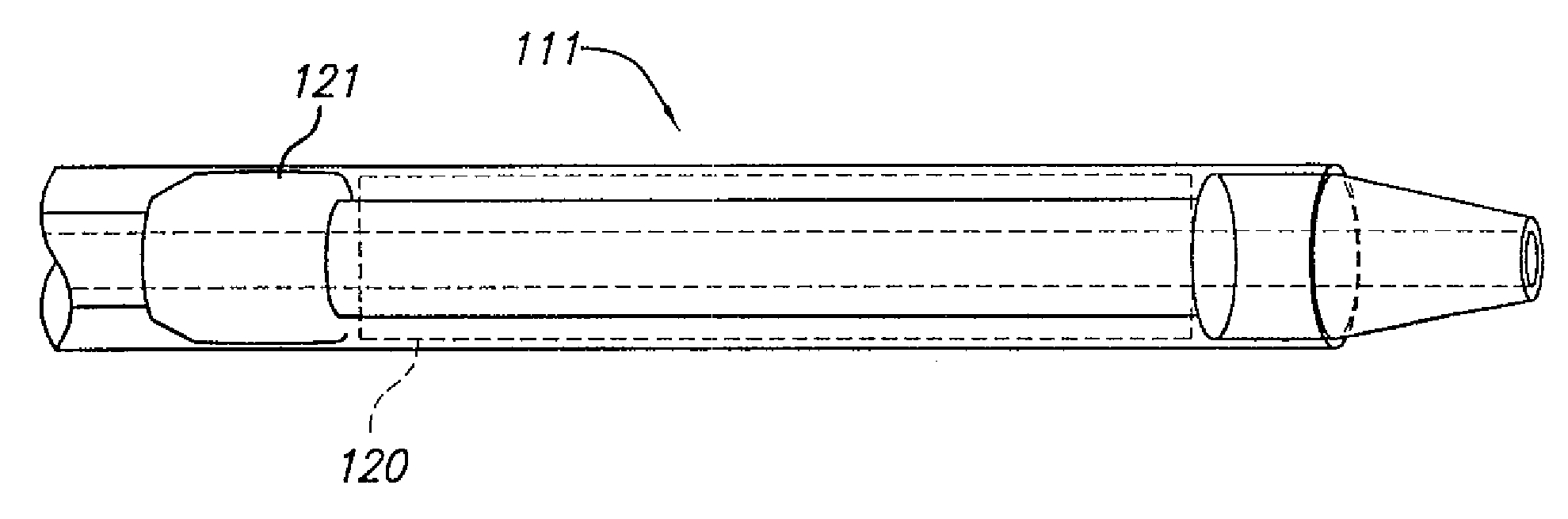
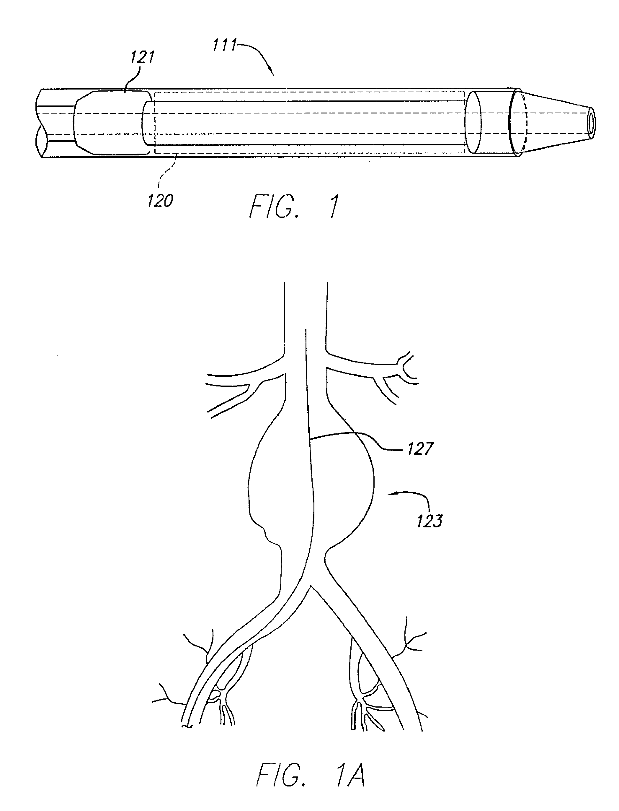
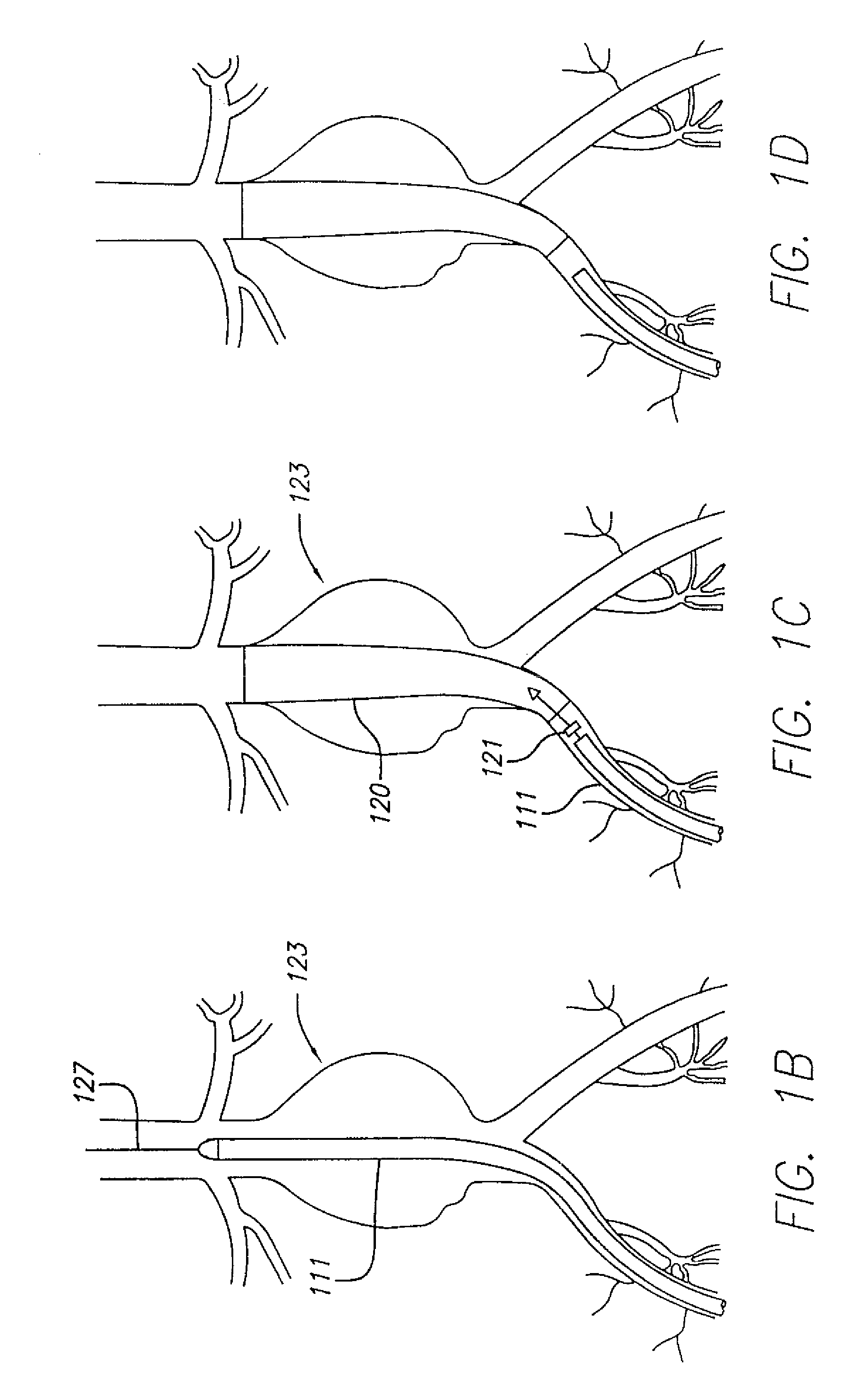
[0082]The present invention relates to systems and methods for accurately delivering and deploying the individual components of a endovascular graft at a treatment site within a patient's vasculature.

[0083]In one aspect, the invention is embodied in a system and method that accomplishes delivering a main graft component within vasculature using a delivery system embodying a jacket which is retracted to deliver the main graft component. The jacket is left within the vasculature and the remaining portions of the delivery system are withdrawn. The jacket is then employed as a sheath and jacket for the advancement and delivery into vasculature of subsequent medical devices. The jacket includes a hemostatic seal that prevents bleeding when exchanging capsules. Each of the subsequent devices is initially held in a capsule that mates with a proximal end of the jacket and is advanced within the jacket using a pusher device. At the time of deployment, the pusher can be held stationary and th...


PUM


Abstract

The present invention embodies delivery systems and methods of packing an initial endovascular graft components for delivery that achieve a smaller delivery profile and reduce redundancy. Delivery systems and methods for packing the initial endovascular graft components for delivery facilitate a reduced delivery profile while allowing reliable positioning of the components before deployment.

Description

BACKGROUND OF THE INVENTION[0001]This invention relates to methods for delivering and deploying modular sections of an endovascular stent / graft for assembly thereof within the vasculature of a patient and specifically to a system for accomplishing the same.[0002]It is well established that various fluid conducting body or corporeal lumens, such as veins and arteries, may deteriorate or suffer trauma so that repair is necessary. For example, various types of aneurysms or other deteriorative diseases may effect the ability of the lumen to conduct fluids and, in turn, may be life threatening. In some cases, the damage to the lumen is repairable only with the use of prosthesis such as an artificial vessel or graft.[0003]For repair of vital lumens such as the aorta, surgical repair is significantly life threatening or subject to significant morbidity. Surgical techniques known in the art involve major surgery in which a graft resembling the natural vessel is spliced into the diseased or ...

Claims


Application Information

Patent Timeline
IPC IPC(8): A61F2/00
CPCA61F2/966A61F2/95A61F2/07A61F2002/9665
Inventor PEREZ, JUAN I.FITZ, MATTHEW J.ECKERT, ROBIN W.IANCEA, OCTAVIANNEWHAUSER, RICHARDPOLLOCK, DAVID T.CHUTER, TIMOTHY A. M.
Owner LIFESHIELD SCI
Why Eureka
Try Eureka