Medium loss high power IBOC combiner

a combiner and high-power technology, applied in the field of medium-loss high-power iboc combiners, can solve the problems of difficult implementation, poor reception of iboc signals, transmitters cannot handle, etc., and achieve the effect of low loss fm analog

Inactive Publication Date: 2011-05-17
MYAT
View PDF16 Cites 2 Cited by
  • Summary
  • Abstract
  • Description
  • Claims
  • Application Information

AI Technical Summary

Benefits of technology

[0020]It is a further object of the invention to provide a high power IBOC combiner with a mild tuned RF filter that provides a response with acceptable FM analog and digital losses.
[0022]It is a yet further object of the invention to provide a method for combining an FM analog signal with a digital signal by using mild tuned bandpass filtering that passes the FM signal with a correctable amount of distortion and only partially reflects the digital signal to produce an output of low loss FM analog and some loss to the digital signals.
[0027]In another aspect of the invention, the apparatus may use mild tuned notch filters that are tuned to partially pass the digital with a correctable amount of distortion, and reflect the FM analog signal, to produce an output of low loss FM analog and some loss to the digital signal.

Problems solved by technology

Currently, digital sidebands are 1 / 100th, or −20 dB, of the power in the analog signal, which often results in poor reception of the IBOC signal.
1) Common Amplification: A low power level combiner is used before the signal is amplified. This method becomes difficult to implement in high power transmitters due to the high peak to average ratio of the digital signal. The transmitters cannot handle the high peak powers.
2) High Level Combining: A high power combining system where a directional coupler is used to inject the digital signal. The analog signal is run through the main line of the coupler while the digital signal is input to the coupled line. The coupling value is typically −10 dB resulting in significant losses (90%) to the digital signal and therefore requires a transmitter with 10 dB more power than required. The lost power is dumped into a dumpy load where it is dissipated into heat. There is also 10% loss of the analog signal which requires existing transmitters to increase power to maintain coverage. Most high power analog transmitters do not have this kind of headroom.
3) Mid Level Combining: A high power combining system where a directional coupler is also used to inject the digital signal. This differs from high level combining in that the digital transmitter has some common amplification (analog and digital) allowing reduced coupling values thereby minimizing digital and analog losses. In mid level combining, the digital losses exceed 3-6 dB. See U.S. Published Patent Application No. 20050190851, to Cabrera.
4) The use of separate antennas or orthogonally fed antennas. The obvious drawback to this strategy is the cost of the duplicative antenna and the transmission equipment needed.
This results in a narrow filter with exceptionally high loss on the analog signal.
When this filter rejection requirement is met, the resulting combiner losses to the analog FM signal is unacceptable.
3 to 6 dB, the analog FM loss was unworkable.
That is, the loss variation is uncorrectable because there is too much delay and amplitude variation.
Also, the mid-band loss and the integrated loss over carrier is too large.
To compensate for these losses, the signal would have to be excessively amplified, and the existing transmitters do not have the head room to provide this amplification.
Moreover, the 8-section filters that would be required make the size of the combiner itself much too large and run too hot due to dissipated losses.

Method used


Image

  • Medium loss high power IBOC combiner
  • Medium loss high power IBOC combiner
  • Medium loss high power IBOC combiner

Examples


Embodiment Construction

Definitions

[0045]For purposes of this invention, the terms “analog FM signal,”“analog signal” and “FM signal” will be synonymous, and will refer to a radio frequency signal that is a frequency modulated analog signal. These terms may be used interchangeably. The term “digital signal” shall mean an RF signal in digital format that shall be at the same frequency as an analog signal.

[0046]The preferred embodiments of the present invention will now be described with reference to the drawings. Identical elements in the various figures are designated with the same reference numerals.

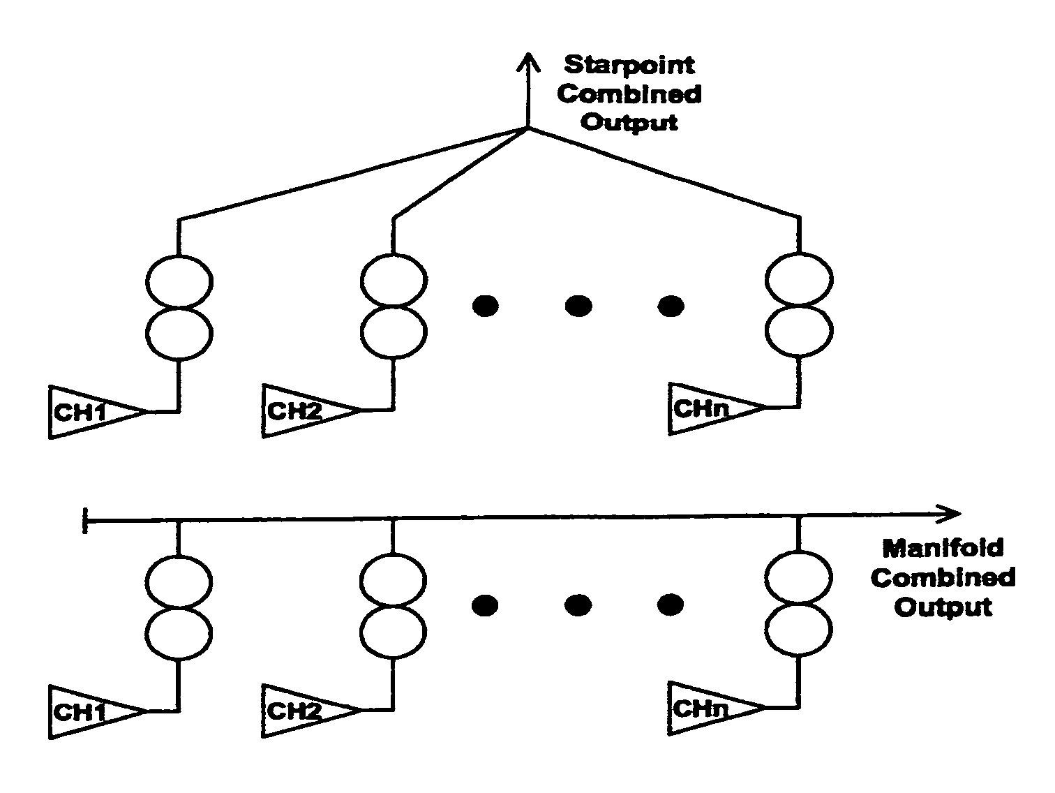
[0047]This invention concerns an apparatus that combines the outputs of an FM analog PA and a digital PA to one output load, which could be a broadcast antenna. The apparatus has two inputs, one for the analog signal and one for the digital signal, and one output that produces an IBOC spectrum for broadcast transmission. The combiner has identical mild tuned bandpass filters that pass the FM signal with a corr...


PUM


Abstract

A method and apparatus are disclosed for combining digital sidebands with an FM analog signal for IBOC transmission by a single antenna. Specifically, a high power filter combiner for combining an FM analog and a digital signal of the same channel, or frequency, is disclosed. The combiner has two inputs that respectively receive an FM analog and a digital signal to be transmitted in the same FM channel. The combiner has mild tuned filters interposed between the inputs and the output which are tuned to pass the FM analog signal while reflecting the digital signal such that the passed FM analog signal and the reflected digital signal combine as IBOC, i.e., an FM analog signal with digital sideband signals. The combined IBOC signal is provided at an output of the combiner, capable for transmission through a single antenna.

Description

CROSS REFERENCE TO RELATED APPLICATION[0001]This application claims priority from U.S. provisional application No. 60 / 958,784, filed Jul. 9, 2007.BACKGROUND OF THE INVENTION[0002]FM radio frequency (“RF”) signals have been traditionally broadcast in an analog format, and therefore transmission systems have largely remained unchanged. See FIG. 1. Recently, the Federal Communications Commission (“FCC”) has accepted a new digital format known as In-Band-On-Channel (“IBOC”), as a method of transmitting digital information on FM radio signals. IBOC requires the simultaneous broadcast of an analog and a digital signal within one channel of the FM band. By utilizing digital subcarriers, see, e.g., FIG. 2, digital information is placed on both sides of the FM analog signal allowing IBOC transmission of the digital information, and alleviating the complications of requiring a separate channel allocated to the digital signal, during the period of transition from analog radio to digital radio....

Claims


Application Information

Patent Timeline
Patent Type & Authority Patents(United States)
IPC IPC(8): H04B17/02H04B17/40
CPCH04H20/30H04L27/12H04H20/46H04H2201/183Y02D30/70
Inventor SMALL, DEREK J.
Owner MYAT
Why Eureka
Try Eureka