Multilayer medical device

a medical device and multi-layer technology, applied in the field of multi-layer medical devices, can solve problems such as mechanical failure, achieve the effects of improving burst strength, and reducing burst pressure and/or puncture resistan

Inactive Publication Date: 2011-05-24
BOSTON SCI SCIMED INC
View PDF169 Cites 31 Cited by
  • Summary
  • Abstract
  • Description
  • Claims
  • Application Information

AI Technical Summary

Benefits of technology

[0033]Embodiments may include one or more of the following advantages. The use of a large number of thin layers distributes stresses, such as cracks, abrasions, etc., with the result that defects are less likely to propagate through the wall and lead to mechanical failure such as bursting. Thus, balloons exhibit enhanced burst strength, burst pressure and / or puncture resistance. The balloons may have thinner walls, while maintaining adequate burst pressure, burst pressure and / or puncture resistance. The balloons, particularly thinner-walled balloons, may be more easily folded about the catheter and more easily self-fold after deflation. The balloons have a softer, more compliant feel. Without increasing balloon wall thickness, the balloons can be more resistant to abrasion or puncture or cutting when used to deliver another implement, such as a stent or graft.
[0034]In certain embodiments, the apparatus used for co-extrusion can be relatively compact. This can be advantageous because it can reduce the residence time of the polymers in the apparatus during co-extrusion, thereby decreasing the likelihood that one or more of the layers will undergo substantial degradation during co-extrusion.
[0035]In certain embodiments, a multilayer article (e.g., a multilayer balloon or a multilayer tube), such as a multilayer article having one or more relatively thin layers, can exhibit good adhesion between at least two adjacent layers, good puncture resistance, high burst pressure, high burst strength, and / or good flexibility.

Problems solved by technology

The use of a large number of thin layers distributes stresses, such as cracks, abrasions, etc., with the result that defects are less likely to propagate through the wall and lead to mechanical failure such as bursting.

Method used


Image

  • Multilayer medical device
  • Multilayer medical device
  • Multilayer medical device

Examples


example 1

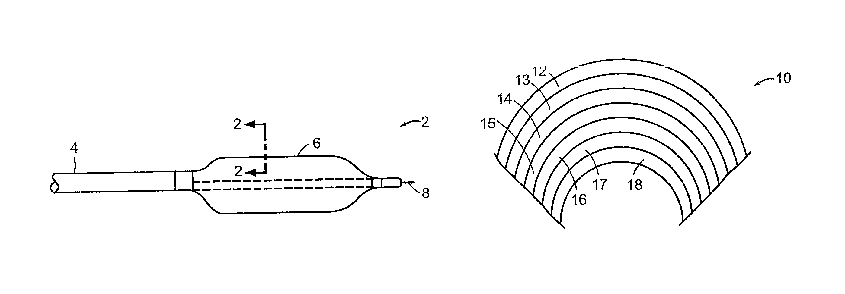
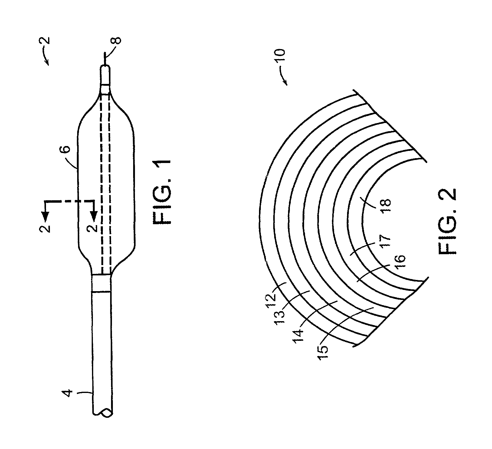
[0098]A thirteen layer tubing was formed by coextruding Pebax 7033 and mixture of Pebax 5533 (85% by weight) and Pebax 2533 (15% by weight) in an alternate layer structure. A soft layer of Pebax 5533 / Pebax 2533 mixture was the outermost layer. The material (by thickness) ratio of Pebax 7033 to the mixture was about 4 to 1. Four 3.25 mm balloons were made from tubing of 0.0170 ID×0.0342 OD (inch). The balloons were formed at 95° C. and 515 psi forming pressure. The balloons had a double wall thickness of 0.00150 inch. The soft polymer layers were about 0.54 micron thick. The hard polymer layers were about 2.54 micron thick. The balloon burst at about 309 psi and calculated burst strength was about 26,250 psi.

example 2

[0099]A seven layer tubing was coextruded with Pebax 7033 and Pebax 5533 in an alternate layer structure. A soft layer of Pebax 5533 was the outermost layer. The material ratio (by thickness) of Pebax 7033 to Pebax 5533 was about 4 to 1. Four 3.0 mm balloons were made from tubing of 0.0200 ID×0.0330 OD (inch). The balloons were formed at 95° C. and at 360 psi forming pressure. The balloons had a double wall thickness of 0.00140 inch. The soft layers were about 1μ thick and the hard layers were about 4μ thick. The balloons burst at about 286 psi and had a calculated burst strength about 26,000 psi.

example 3

[0100]A thirteen layer tubing was formed by coextruding Pebax 7033 and Pebax 5533 in an alternate layer structure. A soft layer of Pebax 5533 was the outermost layer. The material (by thickness) ratio of Pebax 7033 to Pebax 5533 was about 4 to 1. Five 3.0 mm balloons were made from tubing of0.0184 ID×0.0348 OD (inch). The balloons were formed at 95° C. and 400 psi forming pressure. The balloons had a double wall thickness of 0.00140 inch. The soft polymer layers were about 0.5μ thick. The hard polymer layers were about 2.3μ thick. The balloon bursts at about 288 psi and calculated burst strength was about 26,000 psi.


PUM

PropertyMeasurementUnit
thicknessaaaaaaaaaa
thicknessaaaaaaaaaa
thicknessaaaaaaaaaa

Abstract

A medical device such as a tube or a balloon including wall structure with multiple layers. The wall structure can distribute stress, resulting in reduced defect propagation and failure.

Description

CROSS-REFERENCE TO RELATED APPLICATION[0001]This application claims priority under 35 U.S.C. §120 to and is a continuation-in-part of commonly owned U.S. patent application Ser. No. 09 / 517,870, filed on Mar. 2, 2000, and entitled “Multilayer Medical Balloon,” now abandoned, the entire contents of which are hereby incorporated by reference.FIELD OF THE INVENTION[0002]This invention relates to multi-layer medical devices.BACKGROUND OF THE INVENTION[0003]Many medical procedures utilize a balloon catheter to, for example, open an occluded lumen, as in angioplasty, position another medical implement, such as a stent or graft, or selectively block a passageway. In most cases, the balloon is positioned on the end of a long, narrow catheter shaft. The balloon is typically wrapped around the catheter shaft to reduce the radial profile for easier insertion. The catheter is then threaded through the body to position the balloon at a location of treatment and the balloon is inflated. Finally, t...

Claims


Application Information

Patent Timeline
Patent Type & Authority Patents(United States)
IPC IPC(8): A61M25/10A61F2/958A61M25/00B29C48/09B29C48/34
CPCA61M25/1029B29C47/0023B29C47/065B29C47/263B29C47/28A61M25/0045A61M25/0009B29L2031/7542A61M2025/1075B29C47/0026B29C47/26B29K2055/02B29K2067/00B29K2067/006B29K2075/00B29K2077/00B29K2105/0079B29L2022/022B29C48/09B29C48/10B29C48/21B29C48/335B29C48/3363B29C48/34
Inventor CHIN, ALBERT C. C.CHEN, JOHN JIANHUAWANG, YIQUNLODIN, DAVID W.WANG, LIXIAOSAHATJIAN, RONALD A.GULER, ISMAILBURGMEIER, ROBERT
Owner BOSTON SCI SCIMED INC
Why Eureka
Try Eureka