Exothermic welding assembly

a technology of exothermic welding and assembly, which is applied in the direction of alumino-thermic welding apparatus, electric fuze,foundry moulding apparatus, etc., can solve the problem of residual material that must be removed

Active Publication Date: 2011-05-31
HARGER
View PDF11 Cites 18 Cited by
  • Summary
  • Abstract
  • Description
  • Claims
  • Application Information

AI Technical Summary

Benefits of technology

[0002]Exothermic welding has been employed in the past as an effective method of welding two or more members together which may be copper and / or steel, such as cables to cables, cables to ground rods, cables to steel surfaces including plates and pipes, cables to bus bars, cables to rebar and the like. Such exothermic welding eliminates the need for an outside source of heat or power and produces a permanent, corrosion resistant weld which cannot loosen and does not increase electrical resistance.
[0008]It would be desirable if an exothermic welding mold existed which was capable of accommodating at least each of these several exothermic welding procedures as well as others, and which would avoid the need for maintaining an inventory of different molds in order to enjoy the specific advantages of each procedure.

Problems solved by technology

Such exothermic welding eliminates the need for an outside source of heat or power and produces a permanent, corrosion resistant weld which cannot loosen and does not increase electrical resistance.
However, even though the steel bottom of the container may achieve a sufficient temperature to melt when the weld metal is melted, the steel side walls may not, thereby leaving a residue which must be removed from the ignition cavity before the mold can be reused to perform another welding procedure.

Method used


Image

  • Exothermic welding assembly
  • Exothermic welding assembly
  • Exothermic welding assembly

Examples


Embodiment Construction

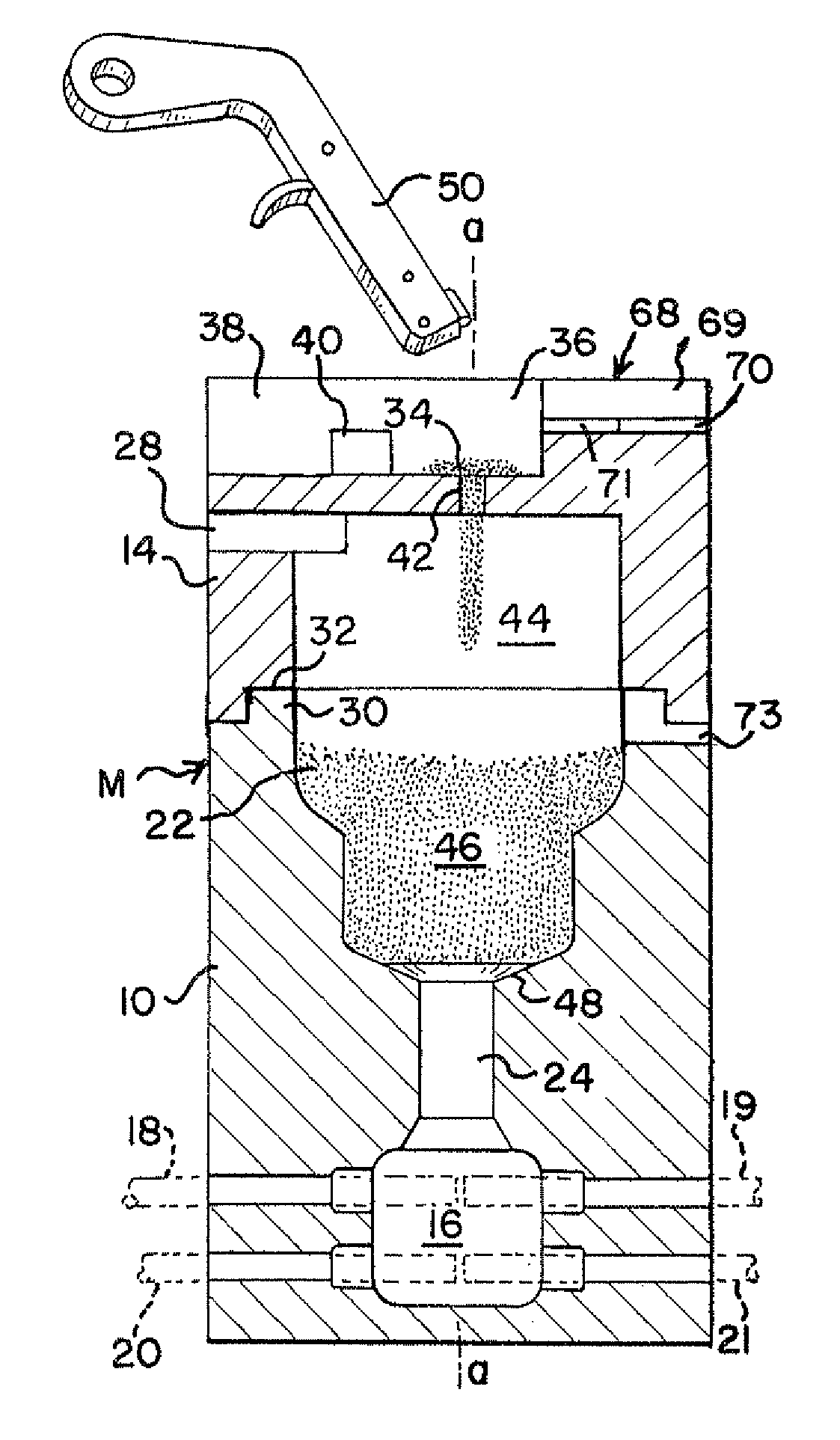
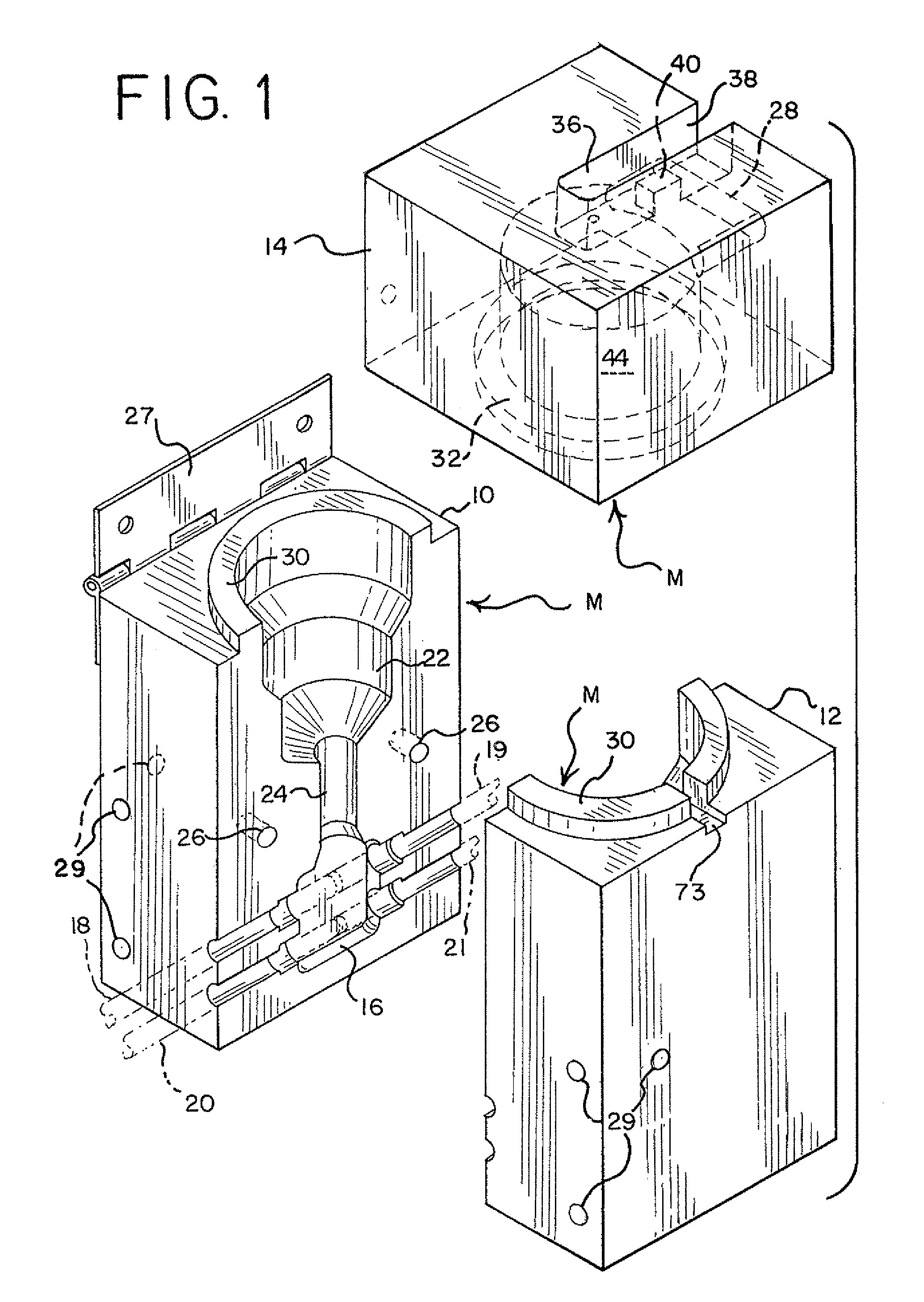
[0046]With particular reference to FIG. 1, a preferred embodiment of exothermic welding assembly of the invention and for practicing the welding procedures of the invention comprises a mold M formed of a suitable material, such as graphite, for withstanding the extremely high temperatures of the exothermic welding process. The mold M as typically employed in exothermic welding is comprised of two mold halves 10 and 12 and a cover 14 as shown in FIG. 1. Mold half 10 includes one half of a weld cavity 16 which, for example as shown in FIG. 1, receives members, such as cables 18, 19, 20 and 21, to position the cables in a closely adjacent relationship to each other to be exothermically welded together in the weld cavity 16. Although the members 18-21 as shown in the drawings as the members to be welded together are cables, the members may be plates, pipes, rebar, etc., or combinations thereof and the weld cavity 16 may open to a face of the mold M to accommodate such other shapes for e...


PUM

PropertyMeasurementUnit
temperaturesaaaaaaaaaa
widthaaaaaaaaaa
angleaaaaaaaaaa

Abstract

An assembly is disclosed for exothermic welding comprising a mold which is formed of a material which withstands exothermic welding temperatures and includes a weld cavity therein for positioning at least two members which are to be exothermically welded together, and an ignition cavity communicating with the weld cavity. The mold is capable of accommodating any one of several exothermic welding procedures which may involve either a flint igniter or the use of an electrical igniter which is readily accommodated by the mold in the performance of several of the procedures. The electrical igniter is formed of a pair of flat, longitudinally extending conductor strips with a sheet of insulation laminated therebetween, a filament adjacent one end of the strips, and one or more positioning tabs adjacent one end of the strips. A cartridge is also provided which contains the weld metal and the electrical igniter and which may be positioned in the ignition cavity of the mold. The cartridge is formed of a material which is consumed during the welding procedure and may contain a plate of a different material adjacent its bottom which melts at a higher temperature than the materials of the cartridge.

Description

BACKGROUND AND SUMMARY OF THE INVENTION[0001]The present invention relates to exothermic welding and an improved assembly, weld metal cartridge and igniter therefor.[0002]Exothermic welding has been employed in the past as an effective method of welding two or more members together which may be copper and / or steel, such as cables to cables, cables to ground rods, cables to steel surfaces including plates and pipes, cables to bus bars, cables to rebar and the like. Such exothermic welding eliminates the need for an outside source of heat or power and produces a permanent, corrosion resistant weld which cannot loosen and does not increase electrical resistance.[0003]In exothermic welding a particulate weld metal is employed which is a mixture of copper oxide and aluminum which, when ignited, produces the following chemical reaction:3Cu2O+2Al→6Cu+Al2O3+heat(4600° F.)[0004]To accomplish such welds the members to be welded together are positioned adjacent to each other utilizing a weld c...

Claims


Application Information

Patent Timeline
Patent Type & Authority Patents(United States)
IPC IPC(8): B23K31/02B28B7/24
CPCB22C9/06B23K23/00
Inventor STIDHAM, CURTIS R.HARGER, MARK S.
Owner HARGER
Why Eureka
Try Eureka