Guide for transmission device

a transmission device and guide technology, applied in the direction of belts/chains/gearrings, mechanical equipment, belts/chains/gears, etc., can solve the problems of troublesome high-precision molding of guide materials, shoe disengagement from supporting base, and easy disengagement of shoe support, so as to facilitate assembly and facilitate assembly. , the effect of easy disengagemen

Inactive Publication Date: 2011-05-31
TSUBAKIMOTO CHAIN CO
View PDF10 Cites 20 Cited by
  • Summary
  • Abstract
  • Description
  • Claims
  • Application Information

AI Technical Summary

Benefits of technology

[0012]The structure by which the shoe is attached to the base frame prevents floating of the shoe relative to the base frame, and allows the shoe to be attached easily to the base frame in the process of assembly of the guide.
[0013]Additionally, because the oblique tongues and the frame positioning surfaces of the strip portions embrace, and press resiliently against, the sides of the base frame, even if a clearance is provided between the sides of the base frame and the engagement portions in order to facilitate assembly, the elasticity of the resin from which the shoe and the engagement portions are formed ensures that the shoe is firmly attached to the base frame while allowing relaxation of dimensional tolerances in the widths of the base frame and the shoe. The relaxation of tolerances results in improved production, increased useful life of the metal mold used to form the shoe, and avoidance of vibration and noise due to backlash in direction of the width of the guide. Additionally uneven wear and formation of traveling lines in the shoe due to shifts in its mounting position can be suppressed.
[0014]Even if the widthwise clearance between the shoe and the base frame increases as a result of thermal expansion under high temperature conditions encountered in the operation of an engine, the frame positioning limiting surfaces of the strip portions and the tongues of the L-shaped engagement portions, which are slanted obliquely toward the sides of the base frame, take up the clearance due to the elasticity of the synthetic resin from which they are formed. Moreover, where the guide is a movable guide, urged by the plunger of a tensioner against a traveling transmission chain or the like, shifts in the position of abutment between the plunger and the guide, due to lateral shifts in the position of the chain, can be avoided so that a pressing force can be more reliably exerted against the guide by the plunger.
[0015]In a preferred embodiment, a bulged portion is formed on the second leg of each L-shaped engagement portion, each bulged portion protruding toward the back surface of the shoe, and engaging the base frame so that the base frame is sandwiched between the bulged portion and the back surface of the shoe. With this structure, even if a clearance is provided between the base frame and the back surface of the shoe for the purpose of facilitating assembly of the guide, the base frame is sandwiched between the bulged portions and the back surface of the shoe by pressure due to the elasticity of the synthetic resin. Here also, dimensional tolerances of the base frame and the synthetic resin shoe can be relaxed, production is facilitated, and the useful life of the metal mold used to form the shoe can be increased. In addition, even if the clearance between the back of the shoe and the front surface of the base frame increases due to thermal expansion under the high temperature conditions encountered in the operation of an engine, vibration noise due to backlash between the shoe and the base frame in the direction perpendicular to the front and back surfaces of the shoe in the shoe can be prevented.

Problems solved by technology

Consequently, the shoe is liable to become disengaged from the supporting base while in operation.
Expansion and contraction is repeated due to a changes in temperature in the engine in which the guide is used, and can result in longitudinal movement of the shoe sufficient to cause the shoe to disengage the supporting base.
However, in order to maintain these strict tolerances, manufacture of the guide requires troublesome high precision molding of the shoe.
Moreover, if strict dimensional tolerances are not maintained in the manufacture of the shoe, a widthwise shift of the shoe relative to the base frame can occur when the shoe is in sliding contact with a traveling transmission chain, generating biased wear, which sometimes results in premature breakage of the shoe.

Method used


Image

  • Guide for transmission device
  • Guide for transmission device
  • Guide for transmission device

Examples


Embodiment Construction

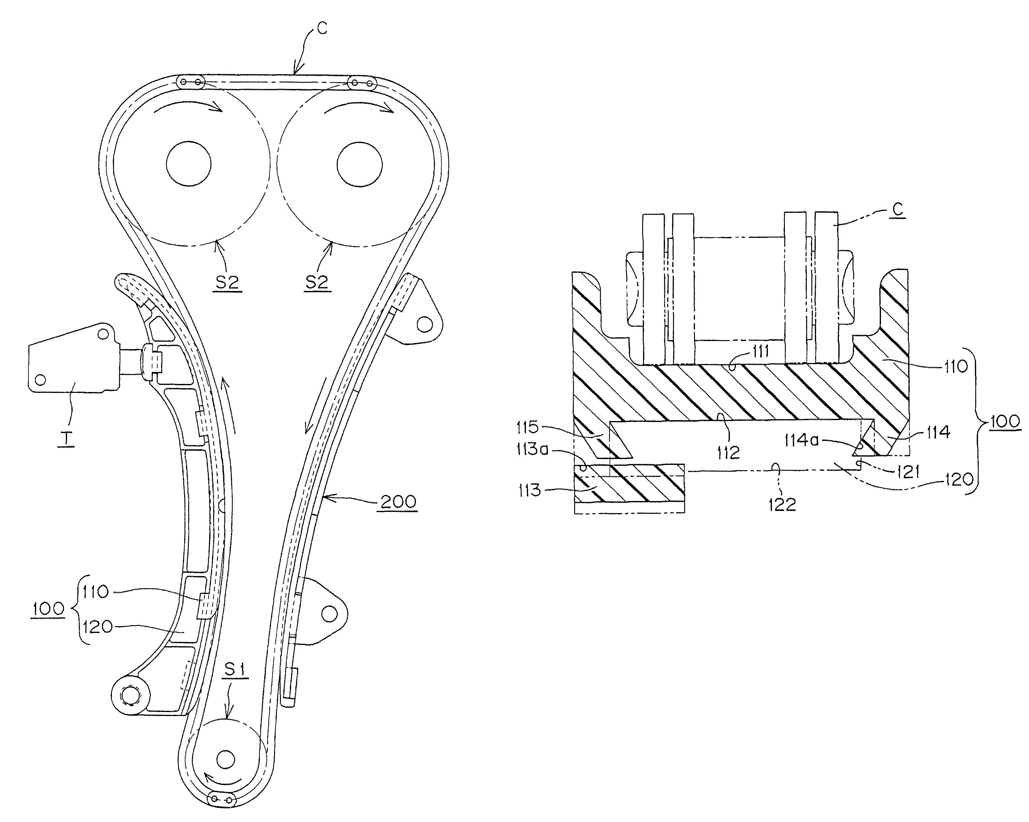
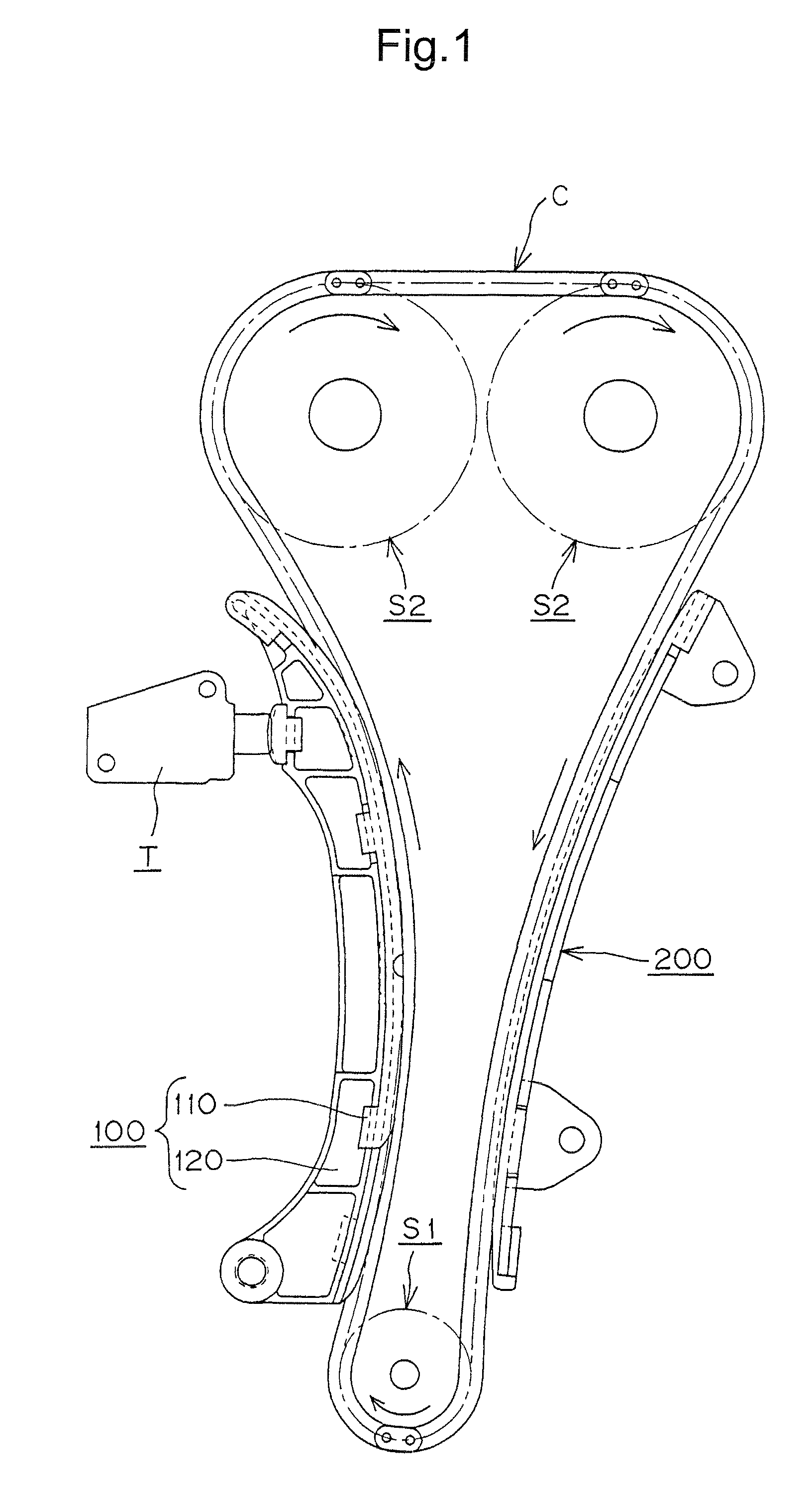
[0030]Here, the guide according to the invention will be described with reference to an embodiment in which the guide is used as a guide for a timing chain in an automobile engine, which transmits power from a driving sprocket on an engine crankshaft to one or more driven sprockets on valve-operating camshafts. The invention is applicable both to a fixed guide on which the chain slides, and to a movable guide, which is used both to guide, and to maintain tension in, the timing chain.

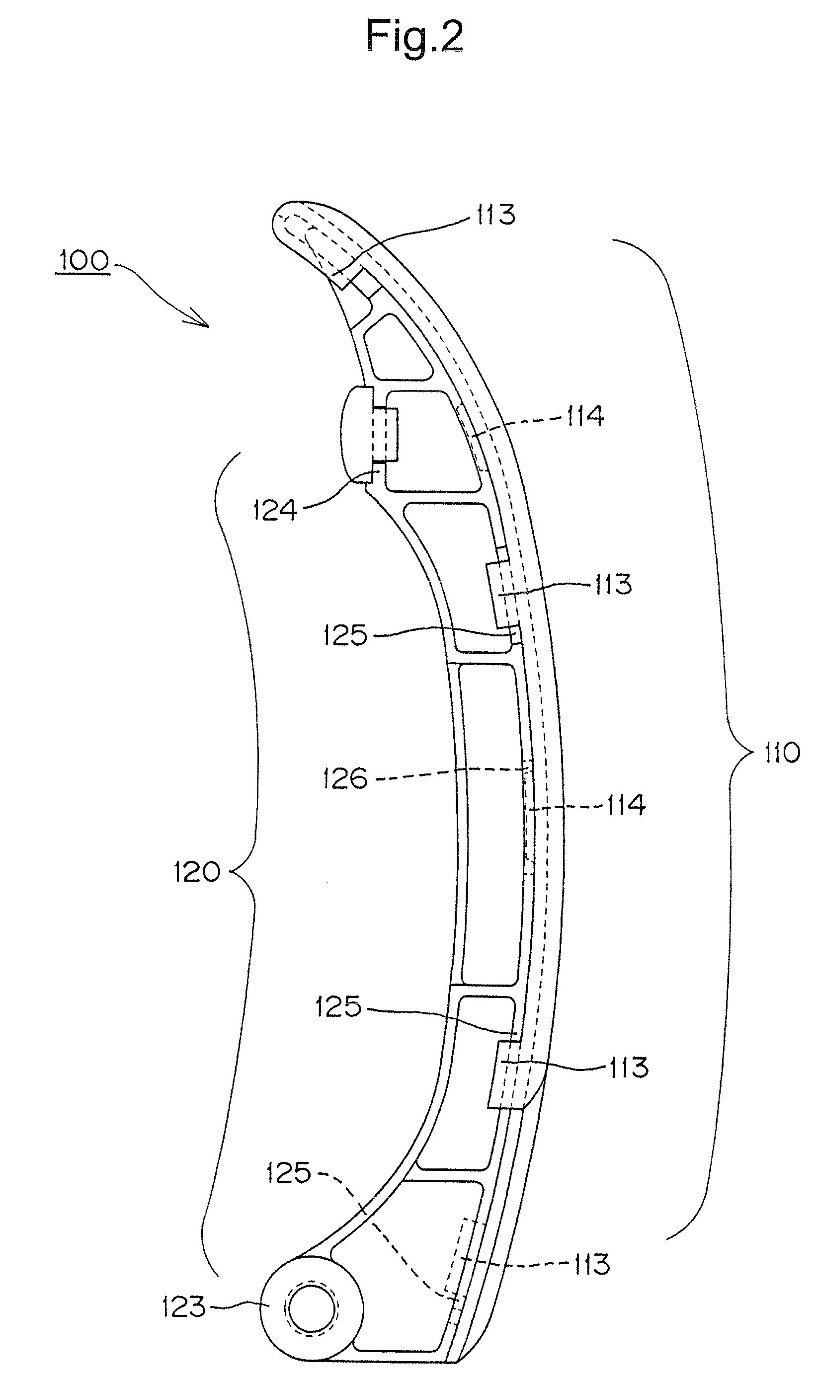
[0031]The principal components of the guide are a shoe and a base frame for supporting the shoe. The shoe is preferably composed of a synthetic resin on which a traveling transmission chain can slide smoothly. Examples of preferred resins are polyamide 6, polyamide 46, polyamide 66, and polyacetal resins. The base frame, is preferably composed of a metal such as aluminum or a synthetic resin material such as glass fiber-reinforced polyamide resin, as these materials exhibit good durability in the high -t...


PUM


Abstract

In an engine timing chain guide composed of a synthetic resin shoe supported on a frame by L-shaped and strip-shaped engagement members integrally molded as unitary parts of the shoe, the L-shaped members are formed with oblique tongues that resiliently engage side edges of the frame member, and the strip-shaped engagement members include surfaces that extend obliquely toward, and resiliently engage, a side edge of the frame member. Laterally extending legs of the L-shaped members are also formed with bulged portions, and the frame member is sandwiched between the bulged portions and a back side of the shoe.

Description

CROSS-REFERENCE TO RELATED APPLICATION[0001]This application claims priority on the basis of Japanese patent application 2007-274327, filed Oct. 22, 2007. The disclosure of Japanese application 2007-274327 is hereby incorporated by reference.FIELD OF THE INVENTION[0002]This invention relates to a guide for a transmission device used as a fixed guide or a movable guide, which guides and tensions a transmission chain in an automobile engine or the like.BACKGROUND OF THE INVENTION[0003]As shown in FIGS. 8 and 9, a known guide, in the form of a tensioner lever 500, is composed of a synthetic resin shoe 510 having integrally molded, L-shaped engagement pieces 511, which engage one side of a shoe-supporting base 520, and a plurality of strip-shaped engagement pieces 512, which engage the opposite side of the base, to prevent the floating of the shoe 510 relative to the base 520. The guide is used to guide, and maintain proper tension in, a transmission chain. Such a guide is described in ...

Claims


Application Information

Patent Timeline
Patent Type & Authority Patents(United States)
IPC IPC(8): F16H7/08
CPCF16H7/18F16H2007/0872F16H7/08
Inventor OOTA, HARUHISAKUROHATA, JUNYA
Owner TSUBAKIMOTO CHAIN CO
Why Eureka
Try Eureka