Vehicle diagnostic tool

a technology for vehicle diagnostics and diagnostic tools, applied in the direction of instruments, nuclear elements, analogue processes for specific applications, etc., can solve problems such as system failure that need immediate attention, and achieve the effect of quickly and accurately diagnosing the power plant system and facilitating connection

Active Publication Date: 2011-05-31
AUTOMOTIVE TEST SOLUTIONS
View PDF33 Cites 55 Cited by
  • Summary
  • Abstract
  • Description
  • Claims
  • Application Information

AI Technical Summary

Benefits of technology

[0016]What was needed is a way in which the automotive technician can easily connect to the automobile's power train control module with a device that could help diagnose the power plant systems quickly and accurately.

Problems solved by technology

A red alert light indicates that the system failure needs immediate attention (e.g., there is a high probability that there is a drivability problem).

Method used


Image

  • Vehicle diagnostic tool
  • Vehicle diagnostic tool
  • Vehicle diagnostic tool

Examples


example 1

[0122]1999 GMC 5.3 liter engine with the air boot leaking bypassing the mass air sensor, which allows the mass air sensor to misread the air entering the engine.

[0123]VI Injector=5 lb per hour.

[0124]Actual Injector On Time:[0125]3480 RPM÷60 sec=58 RPS[0126]58 RPS÷4=14.5SPS[0127]Actual air rate 105GPS÷1405SPS=7.24GPS[0128]7.24GPS÷14.7AF=0.492FR[0129]0.492FR÷0.036 injector flow rate=13.68 ms[0130]13.68 ms+1 ms injector turn on time=14.68 ms[0131]14.68 ms×1.186FT=17.41 ms actual injector on time

[0132]Calculated Injector On Time:[0133]3480 RPM÷60 sec=58 RPS[0134]58 RPS÷4=14.5SPS[0135]Calculated air rate 127.5GPS÷1405SPS=8.79GPS[0136]8.79GPS÷14.7AF=0.598FR[0137]0.598FR÷0.036 injector flow rate=16.61 ms[0138]16.61 ms+1 ms injector turn on time=17.61 ms[0139]17.61 ms×1FT=17.61 ms calculated injector on time

[0140]Injector on time difference=0.2 ms. The percentage difference is 1.12. This indicates that the problem is a MAF sensor misreading.

example 2

[0141]Malibu 3.1 liter engine; purge control making fuel system rich; fuel problem;

[0142]VI Injector=5 lb per hour

[0143]Actual Injector On Time:[0144]RPM÷60 sec=58.33RPS[0145]58.33RPS÷4=14.58SPS[0146]Actual air rate 34.87GPS÷14.58SPS=2.39GPS[0147]2.39GPS÷14.7AF=0.162FR[0148]0.162FR÷0.036 injector flow rate=4.51 ms[0149]4.51 ms+1 ms injector turn on time=5.51 ms[0150]5.51 ms×0.8FT=4.40 ms actual injector on time

[0151]Calculated Injector On Time:[0152]3500 RPM÷60 sec=58.33RPS[0153]58.33RPS÷4=14.58SPS[0154]Calculated air rate 33.88GPS÷14.58SPS=2.32GPS[0155]2.32GPS÷14.7AF=0.158FR[0156]0.158FR÷0.036 injector flow rate=4.39 ms[0157]4.39 ms+1 ms injector turn on time=5.39 ms[0158]5.39 ms×1FT=5.39 ms calculated injector on time

[0159]Injector on time difference=0.99 ms. The percentage difference is 18. This would indicate that the problem is in the fuel delivery system.

[0160]If enhanced data is available (e.g., OBDII enhanced) the Simulated Injector value would correspond to the actual injec...


PUM


Abstract

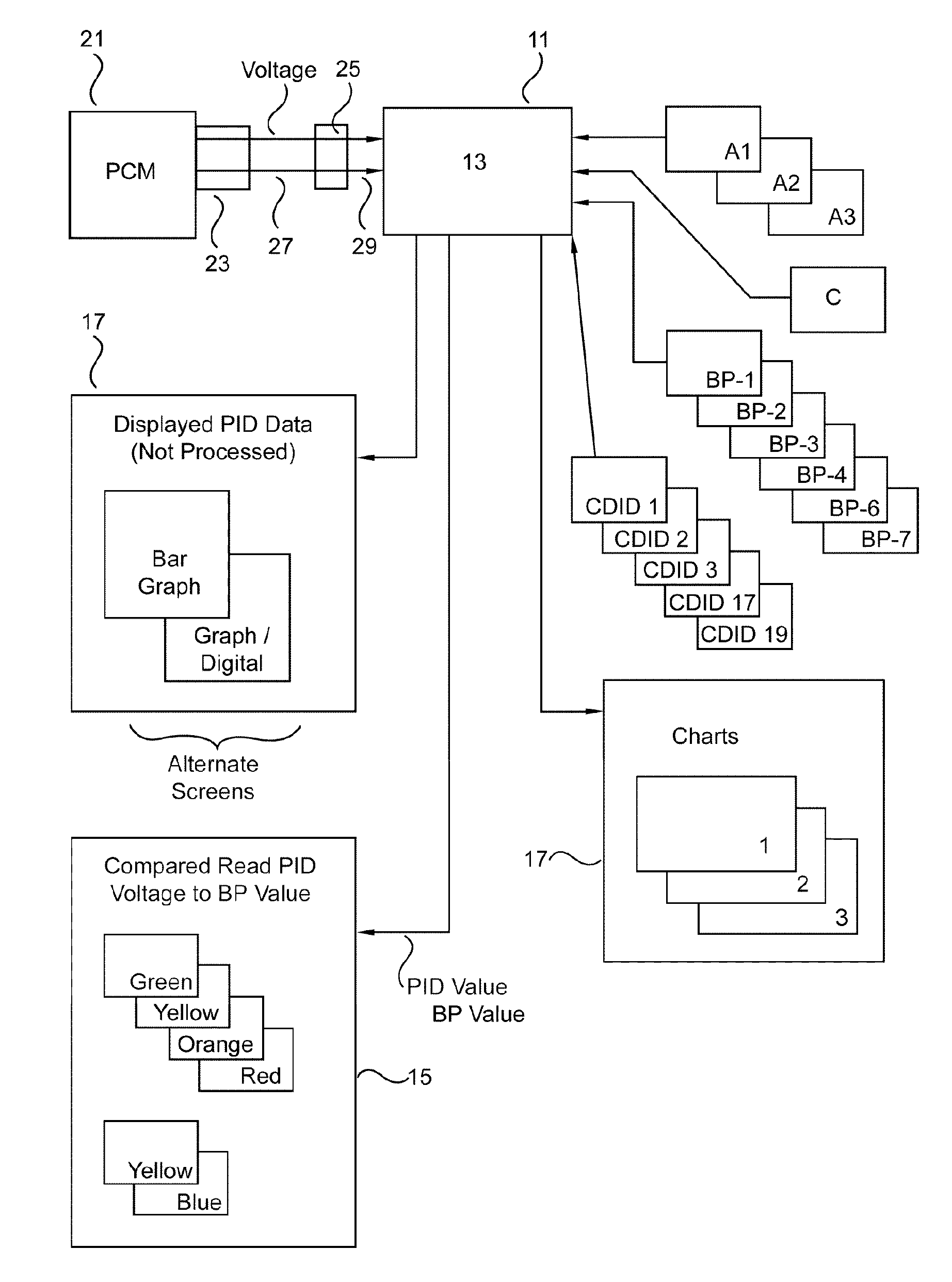
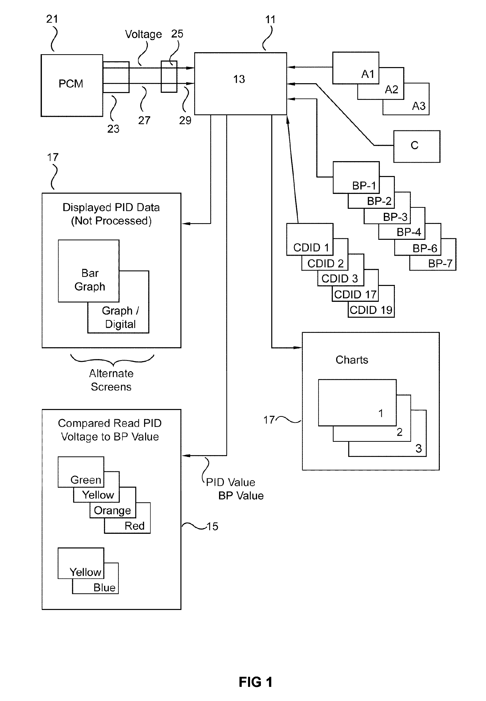
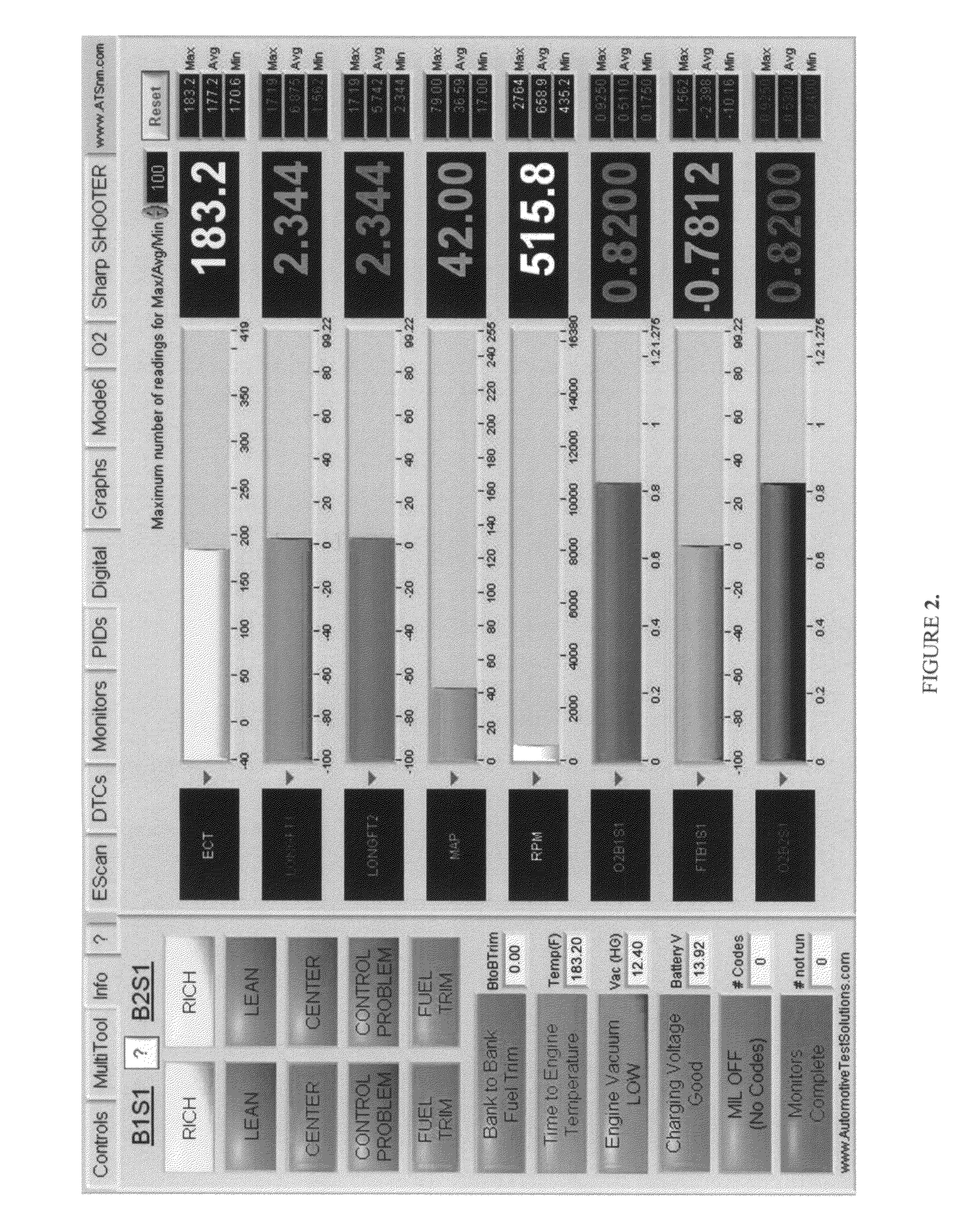
An analysis tool which extracts all the available parameter identifications (i.e. PIDS) from a vehicle's power train control module for diagnostic decisions. This is done by checking these PIDS and other information (e.g., calculated PIDS, Break Points, charts and algorithms) in three states; key on engine off, key on engine cranking, key on engine running. In all three modes the tool is comparing the live data from PIDS and voltage to the other information (e.g, Break Points). If any of this data are outside the programmed values a flag is assigned to the failure or control problem. The relationship between a particular PID and its associated preprogrammed value(s) may be indicated by a light. The depth of the problem (if any) is conveyed by the color of the light. Also included are tests/charts for fuel trim, engine volumetric efficiency, simulated injector, power, catalyst efficiency, and engine coolant range.

Description

CLAIM OF PRIORITY[0001]This application is a continuation of and claims the priority of provisional application Ser. No. 60 / 812,525, filed Jun. 8, 2006.FIELD OF THE INVENTION[0002]This invention relates to automotive diagnostic tools, particularly an analysis tool that will interface with the power train control module and alert the automotive technician to problems with the engine control system and / or the associated engine and / or other power plant systems, to permit such technician to zero in on such problems.BACKGROUND OF THE INVENTION[0003]With increasing government demands on emission control systems and fuel mileage concerns, the power plant of a vehicle has become a high tech engineering marvel. This, in turn, means that the automotive technician is faced with increasing difficulties of diagnosing and repairing complicated systems. Repairs must be completed in a timely manner which has become a problem for many automotive repair shops.[0004]The modern vehicle (1996 and later ...

Claims


Application Information

Patent Timeline
Patent Type & Authority Patents(United States)
IPC IPC(8): G01M15/00G06F19/00G16B45/00
CPCG01M15/04G07C5/0808G01M15/05
Inventor PEDERSON, NEAL R.THOMPSON, BERNIE C.
Owner AUTOMOTIVE TEST SOLUTIONS
Why Eureka
Try Eureka