Rotor for rotating electrical machine and method of manufacturing same

a technology of rotating electrical machines and rotating rotors, which is applied in the direction of rotating parts of magnetic circuits, magnetic circuit shapes/forms/construction, magnetic bodies, etc., can solve the problem of difficult passage of deformed insulating tubes through the neck

Active Publication Date: 2011-06-07
DENSO CORP
View PDF17 Cites 6 Cited by
  • Summary
  • Abstract
  • Description
  • Claims
  • Application Information

AI Technical Summary

Benefits of technology

[0023]With the above configuration, the lead can be easily and reliably hooked (or held) by the first and second hook portions. Consequently, it is possible to reliably prevent the lead from being loosened. Further, in operation of the rotating electrical machine, it is also possible to prevent the lead from being broken due to a centrifugal force and a repeated tensile force received from the pole cores.
[0071]With the above method, since movement of the winding start lead of the field coil is restricted by the winding start-side restricting member, the winding portion of the field coil can be reliably wound around the body of the insulating bobbin without causing the winding start lead to be loosened. Moreover, the insulating tubes can be easily put on the corresponding leads of the field coil.

Problems solved by technology

Moreover, once has been pushed into the inside of the second groove, it is difficult for the deformed insulating tube to get out through the neck.

Method used


Image

  • Rotor for rotating electrical machine and method of manufacturing same
  • Rotor for rotating electrical machine and method of manufacturing same
  • Rotor for rotating electrical machine and method of manufacturing same

Examples


first embodiment

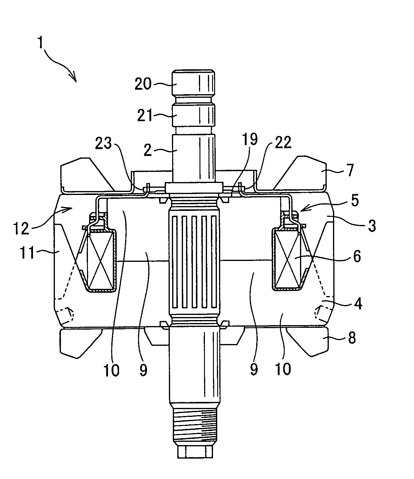
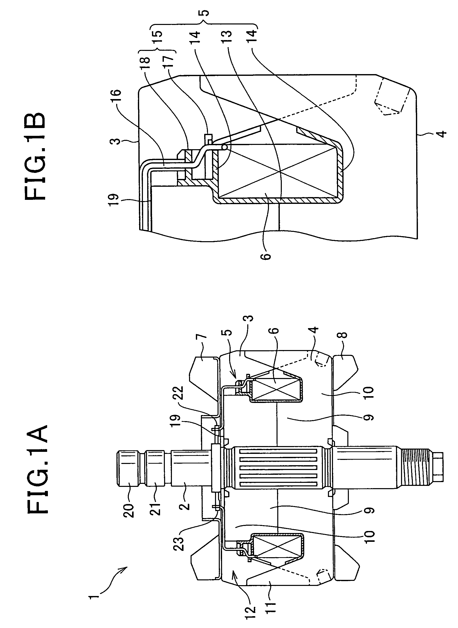
[0097]FIG. 1A shows the overall structure of a rotor 1 according to the first embodiment of the invention.

[0098]The rotor 1 is designed to be used in an automotive alternator to create a rotating magnetic field. More specifically, the rotor 1 is designed to be rotatably supported by a frame (not shown) of the alternator and to be driven by an internal combustion engine of a motor vehicle.

[0099]As shown in FIG. 1A, the rotor 1 includes a shaft 2, a pair of Lundell-type pole cores 3 and 4 (i.e., rotor cores) press-fit on the shaft 2, an insulating bobbin 5 fit on the pole cores 3 and 4, a field coil 6 wound around the insulating bobbin 5, and cooling fans 7 and 8 fixed respectively to axial end faces of the pole cores 3 and 4.

[0100]The pole cores 3 and 4 have the same shape and size. Each of the pole cores has a cylindrical boss portion 9, a disc portion 10, and a plurality of claw portions 11. The boss portion 9 is coaxially press-fit on the shaft 2. The disc portion 10 extends radia...

second embodiment

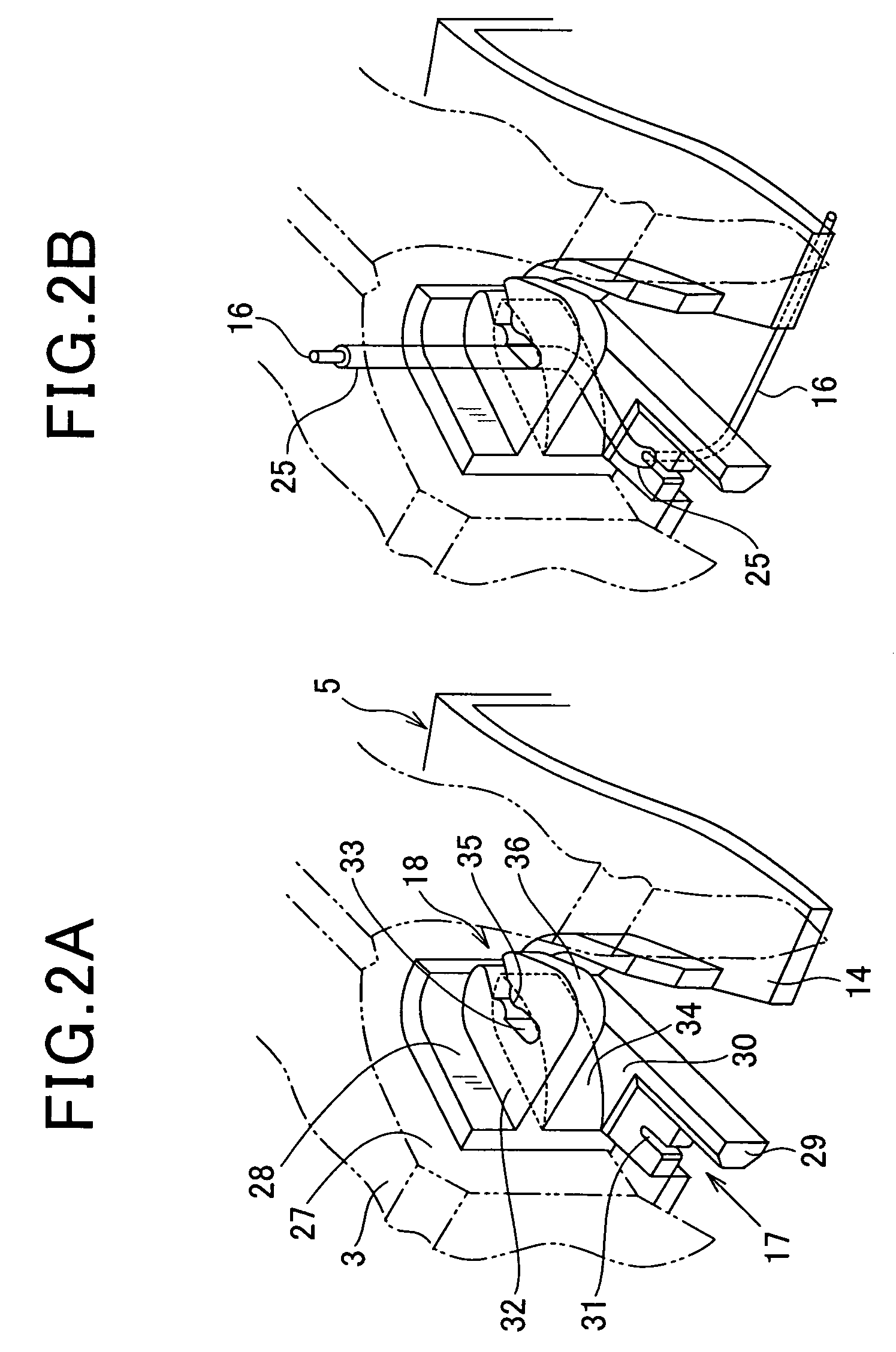
[0140]This embodiment illustrates hook mechanisms for hooking the leads 16 of the field coil 6 which are different from the hook mechanisms according to the first embodiment.

[0141]In addition, in the present embodiment, the hook mechanisms for hooking the winding start and winding end leads 16 of the field coil 6 are also identical to each other. Therefore, for the sake of simplicity, only the winding end lead 16 and the hook mechanism therefore will be described hereinafter.

[0142]As shown in FIGS. 5A, 5B, and 6, in the present embodiment, the flange 14 of the insulating bobbin 5 is formed with a V-shaped wall portion 28, a first restricting portion 51, a second restricting portion 52, and fan-shaped portions 30, 32, and 39.

[0143]The wall portion 28 is fit to the surface 27 of the V-shaped groove 12 formed between the claw portions 11 of the pole core 3 and protrudes axially outward from the flange 14 by a predetermined distance.

[0144]The first restricting portion 51 protrudes from ...

third embodiment

[0177]This embodiment illustrates hook mechanisms for hooking the leads 16 of the field coil 6 which are modified from the hook mechanisms according to the second embodiment.

[0178]In addition, in the present embodiment, the hook mechanisms for hooking the winding start and winding end leads 16 of the field coil 6 are also identical to each other. Therefore, for the sake of simplicity, only the winding end lead 16 and the hook mechanism therefore will be described hereinafter.

[0179]As shown in FIGS. 8A, 8B, and 9, in the present embodiment, the flange 14 of the insulating bobbin 5 is formed with a V-shaped wall portion 28, a first restricting portion 51, a second restricting portion 52, fan-shaped portions 30 and 39, and protrusions 61 and 62.

[0180]The wall portion 28 is fit to the surface 27 of the V-shaped groove 12 formed between the claw portions 11 of the pole core 3 and protrudes axially outward from the flange 14 by a predetermined distance.

[0181]The first restricting portion ...


PUM

PropertyMeasurementUnit
widthaaaaaaaaaa
diameteraaaaaaaaaa
thicknessaaaaaaaaaa

Abstract

In a rotor for a rotating electrical machine, a flange of an insulating bobbin is formed with a first hook portion and a second hook portion. The first hook portion directs a lead of a field coil both against the winding direction of the field coil and radially inward. The first hook portion has a first groove in which is hooked a proximal portion of the lead. The second hook portion directs the lead axially outward. The second hook portion has a second groove which has an open end on a radially inner periphery of the second hook portion, a closed end positioned radially outward of the open end, and a neck between the open and closed ends. The second hook portion has an intermediate portion of the lead hooked in the second groove between the neck and closed end of the second groove.

Description

CROSS-REFERENCE TO RELATED APPLICATION[0001]This application is based on and claims priority from Japanese Patent Application No. 2008-71049, filed on Mar. 19, 2008, the content of which is hereby incorporated by reference in its entirety into this application.BACKGROUND OF THE INVENTION[0002]1. Technical Field of the Invention[0003]The present invention relates generally to rotors for rotating electrical machines, such as electric generators and motors, and methods of manufacturing the rotors.[0004]More particularly, the invention relates to rotors for automotive alternators, which include Lundell-type pole cores as rotor cores, and their manufacturing methods.[0005]2. Description of the Related Art[0006]Conventionally, a rotor for an automotive alternator generally includes a pair of Lundell-type pole cores as rotor cores. The pole cores are press-fit on a shaft of the rotor so that they are opposed to each other in the axial direction of the shaft, forming a hollow space therebet...

Claims


Application Information

Patent Timeline
Patent Type & Authority Patents(United States)
IPC IPC(8): H02K19/26H02K3/46H02K11/00H02K15/02H02K1/28H01F7/06
CPCH02K3/528Y10T29/49012Y10T29/49073Y10T29/49071
Inventor TOKIZAWA, TAKASHI
Owner DENSO CORP
Why Eureka
Try Eureka