Configurable imaging system

a technology of imaging system and configuration, applied in the field of imaging system, can solve the problems of increased weight, limited projector resolution due to light valve/panel design, and significant cost associated with higher resolution, and achieve the effects of improving brightness, improving resolution, and low cos

Inactive Publication Date: 2011-06-14
CHRISTIE DIGITAL SYST USA INC
View PDF27 Cites 7 Cited by
  • Summary
  • Abstract
  • Description
  • Claims
  • Application Information

AI Technical Summary

Benefits of technology

[0008]The imaging system set forth herein below establishes a new paradigm wherein improvement in brightness is achieved without increased power requirements (e.g. the increase is in the order of nits rather than lumens), at a required pixel pitch (pixels per mm) rather than increased resolution, and at very low cost.
[0009]The imaging system set forth herein results in a new paradigm that uses low resolution (inexpensive) panels with low power illumination in order to achieve very low cost projection displays. The microtile units set forth herein are reusable and configurable to enable low cost displays of almost any size and shape, without sacrificing image quality and brightness.

Problems solved by technology

This paradigm has served the industry well, but has a number of drawbacks which include: the significant cost associated with higher resolutions, limitations in projector resolution due to light valve / panel design, increased weight, increased cost and increased noise levels associated with cooling systems necessary to accommodate high power illumination.

Method used


Image

  • Configurable imaging system
  • Configurable imaging system
  • Configurable imaging system

Examples


Embodiment Construction

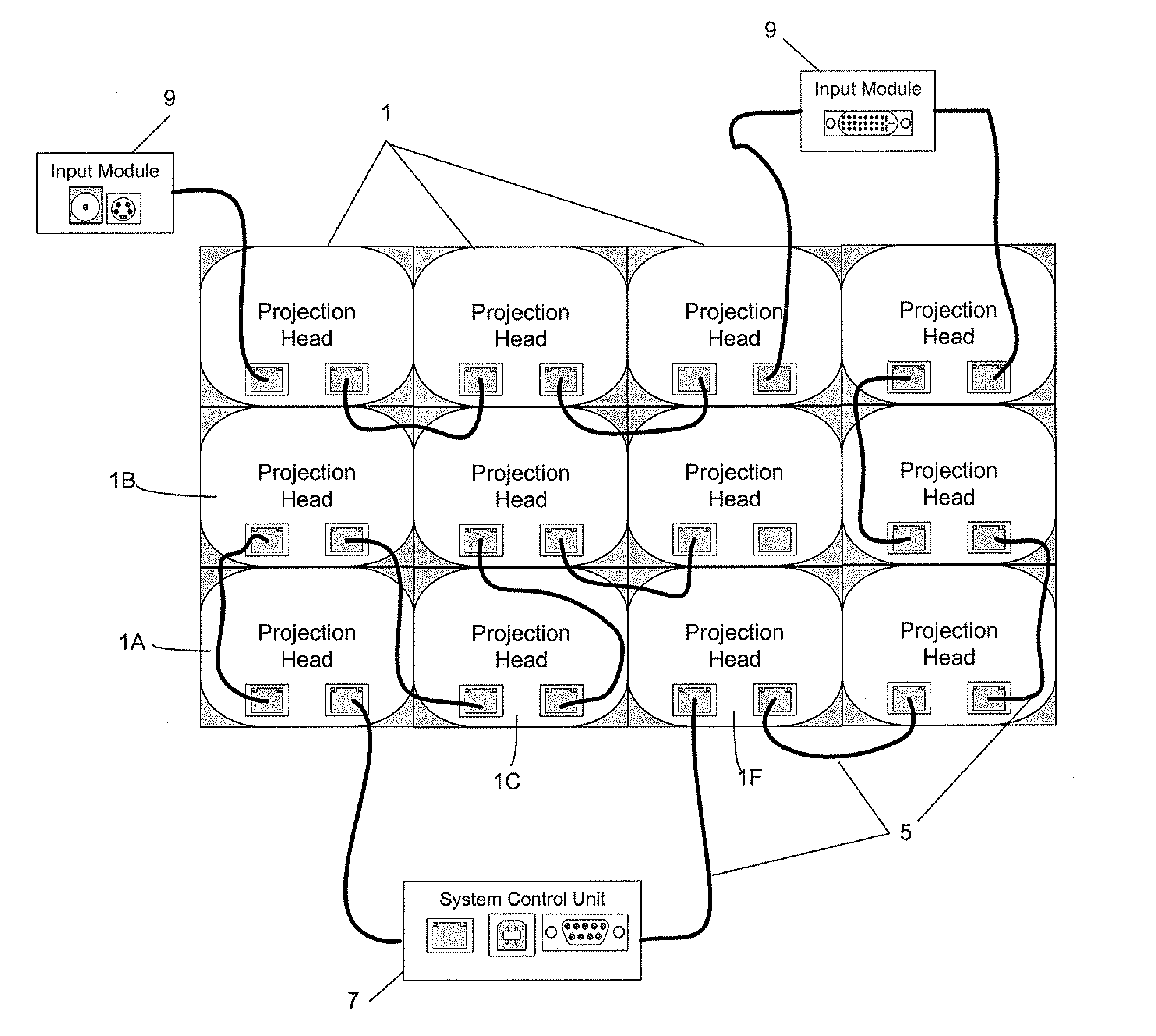
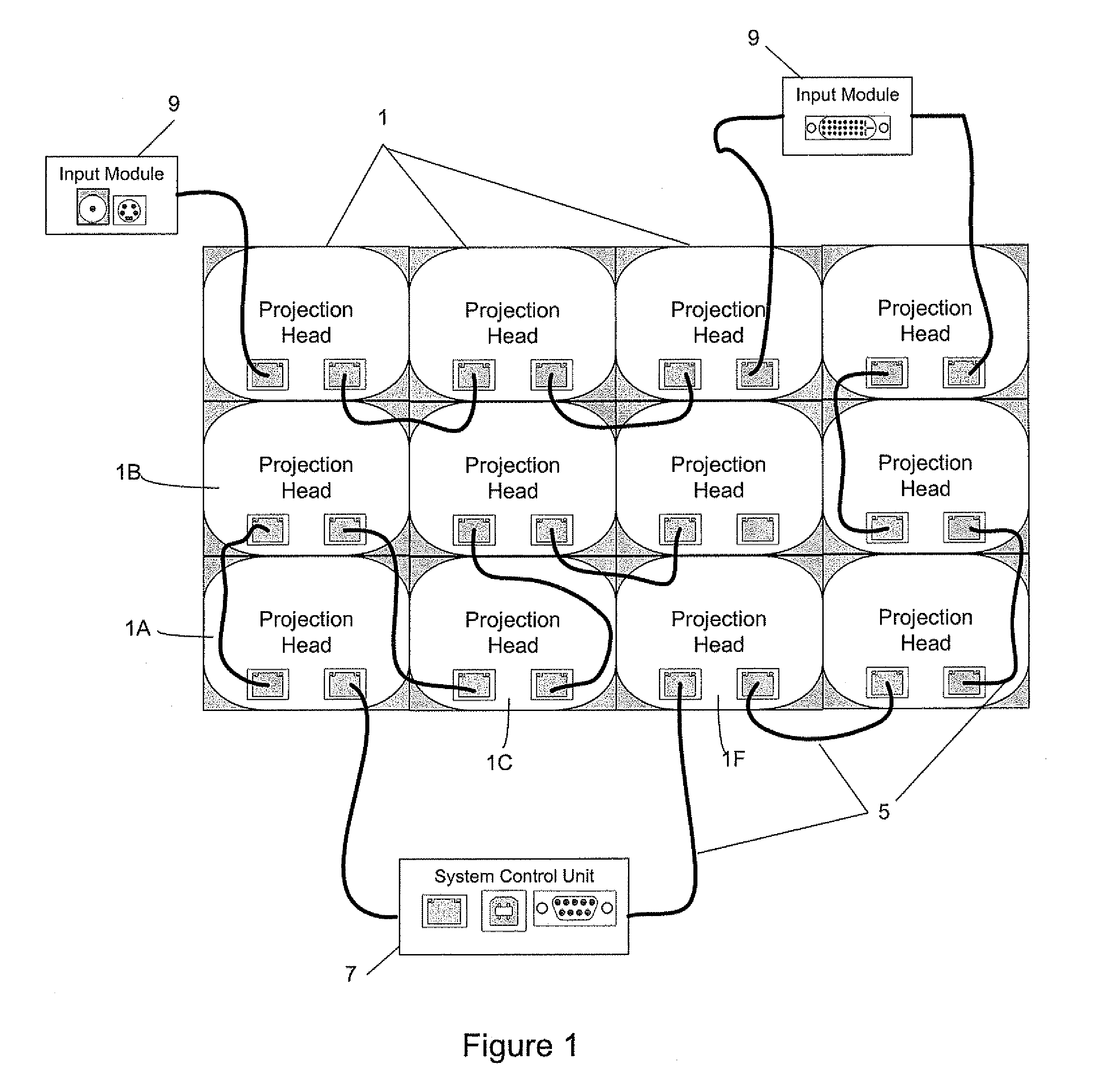
[0020]In FIG. 1, an exemplary imaging system is shown comprising a plurality of series connected microtile units or projection heads 1 assembled to form an array. Cables 5 are used to connect the microtile units 1 in any sequence. According to one embodiment standard CAT 5 cabling is used having four twisted wire pairs for data and command message transmission, wherein command messages are embedded in the blanking interval of a video data stream. Data transmission preferably occurs at a rate of about 5 Gpbs.

[0021]Each microtile unit 1 contains a light engine and circuitry (including, for example, a microprocessor, RAM frame buffer and video processing to provide image capture, resizing, color matching, edge blending, etc.), discussed in greater detail below with reference to FIGS. 7 and 8. Data received from an adjacent microtile unit 1 via cable 5 is buffered and retransmitted to the next series-connected microtile unit 1 (or system control unit 7 or input module 9). The video proc...


PUM


Abstract

An imaging system, comprising an image source and a plurality of microtile units for generating respective portions of an image, each microtile unit including a plurality of coupling mechanisms for connection to a plurality of other microtile units such that the microtile units may be arranged in multiple geometrical configurations, and each microtile unit including circuitry for communication with the other microtile units to control generation of each respective portion of the image.

Description

BACKGROUND[0001]1. Field[0002]The following is directed in general to imaging systems, and more particularly to an imaging system having a plurality of microtile units for generating respective portions of a composite image.[0003]2. Description of the Related Art[0004]A large number of applications and potential applications exist for imaging systems such as projection displays that are used to display information. Such applications include, but are not limited to, general indoor signage (e.g. shopping malls, arcades, etc.), transportation signage (e.g. arrival / departure times, etc.), in-lobby signage for office buildings, control rooms, restaurants signage, etc.[0005]The currently prevailing paradigm in the projection display industry is that improvement must be based on higher light power (lumens) at higher resolutions and progressively lower cost. This paradigm is based on the concept that higher resolution and higher power are necessary to develop larger displays with acceptable...

Claims


Application Information

Patent Timeline
Patent Type & Authority Patents(United States)
IPC IPC(8): G09G5/00
CPCG06F3/1446G09F9/3026H04N9/12G09G2300/026G09G2370/04G09G2360/14
Inventor PERKINS, MICHAELRUSHBY, ROBERT
Owner CHRISTIE DIGITAL SYST USA INC
Why Eureka
Try Eureka