Pump probe measuring device and scanning probe microscope apparatus using the device

a technology of scanning probe and measuring device, which is applied in the direction of force measurement by measuring optical property variation, instruments, nuclear engineering, etc., can solve the problems of increasing the overall cost of the measurement apparatus and increasing the noise level, and achieves high accuracy, short and long relaxation time, and stable measurement. the effect of weak signals

Inactive Publication Date: 2011-06-14
G THERANOSTICS CO LTD
View PDF16 Cites 5 Cited by
  • Summary
  • Abstract
  • Description
  • Claims
  • Application Information

AI Technical Summary

Benefits of technology

In the field of the time-resolved measurement using pulse laser including the fs region, the present invention provides the pump probe measuring device for measuring and analyzing ultrafast physical phenomena, as well as the time-resolved scanning probe microscope apparatus using this measuring device, to measure the very weak signals highly accurately and stably over a wide measurement range, including phenomena having short and long relaxation time, without modifying the intensity of the light to be applied.

Problems solved by technology

This increases noise level.
In addition, since this new delay time modulation method requires two expensive laser oscillators, which must be oscillated synchronized, the overall cost of the measurement apparatus increases.

Method used


Image

  • Pump probe measuring device and scanning probe microscope apparatus using the device
  • Pump probe measuring device and scanning probe microscope apparatus using the device
  • Pump probe measuring device and scanning probe microscope apparatus using the device

Examples


Embodiment Construction

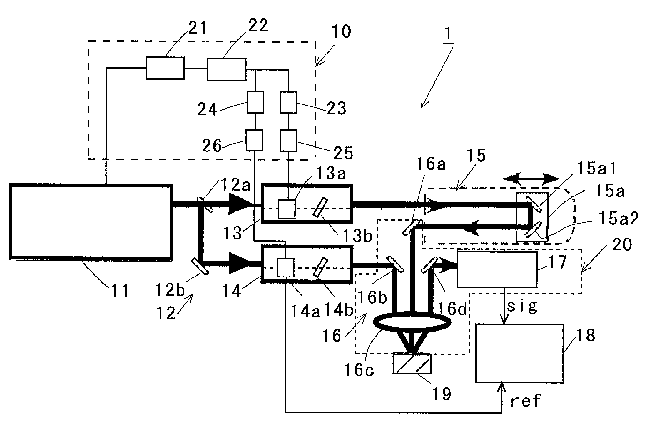
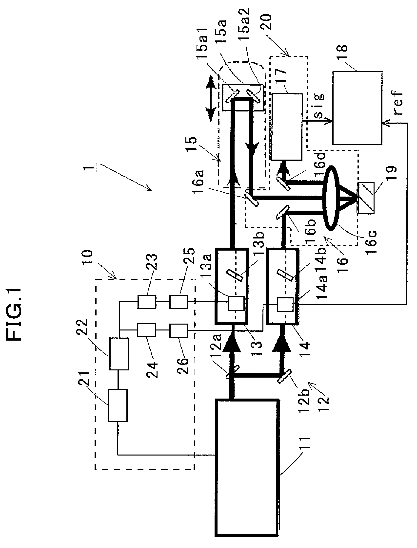
Examples of the delay-time-modulated pump probe measuring device according to the present invention will be described below.

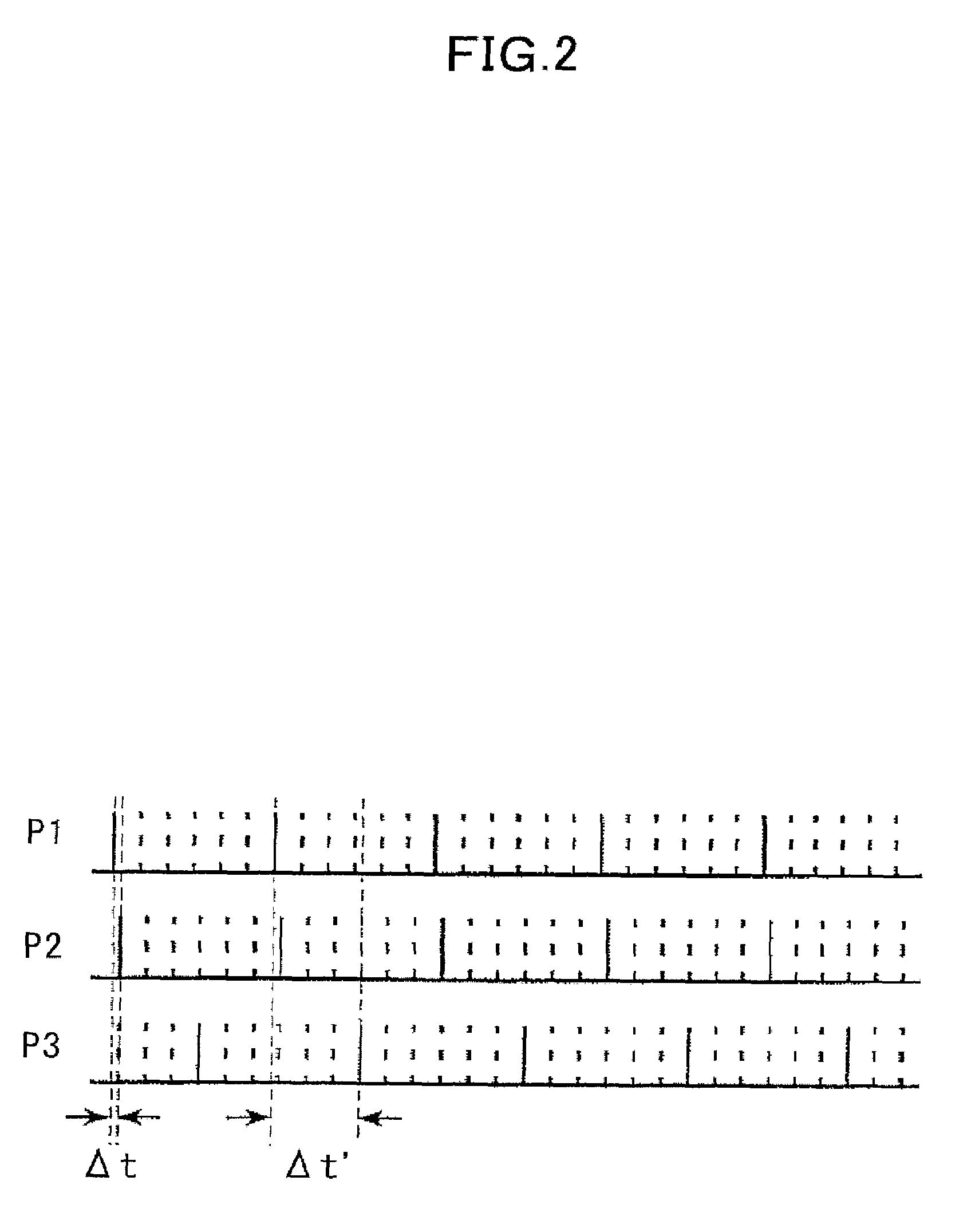
The basic principle of the measurement procedure of the delay-time-modulated pump probe measuring device according to the present invention is the same as that of the widely used conventional delay-time-modulated pump probe measuring device, but innovative improvement has been made to the modulation method. Even if such improvement is made, the system operates normally based on the basic operation principle governing the conventional systems.

Of the embodiments shown above, the configuration of the scanning probe microscope apparatus 50 as shown in FIG. 7 will be described in details below.

The ultrafast time-resolved scanning tunneling microscope 50 is composed by combining the rectangular-wave-based delay time modulation system using pulse pickers, which is the core of the present invention, and the conventional scanning tunneling microscope.

First, the typical ...


PUM

PropertyMeasurementUnit
modulation frequencyaaaaaaaaaa
relaxation timeaaaaaaaaaa

Abstract

A pump probe measuring device (1) includes an ultrashort optical pulse laser generator (11) for generating a first ultrashort optical pulse train, which becomes a pump light, and a second ultrashort optical pulse train, which becomes a probe light, a delay time adjusting unit (15) for adjusting a delay time between ultrashort optical pulse trains, a first pulse picker and a second pulse picker (13, 14) for accepting each of the first and the second ultrashort optical pulse trains and allowing only one pulse to be transmitted at an arbitrary repetition periodicity, thus reducing the effective repetition frequency of the optical pulses, a delay time modulation unit (10) for periodically changing a position through which pulses are transmitted by the first and the second pulse pickers (13, 14), an irradiation optical system (16) for applying pump light and probe light to a sample (19), a measuring unit (20) for detecting probe signals from a sample (19), and a lock-in amplifier (18).

Description

TECHNICAL FIELDThe present invention relates to a pump probe measuring device for measuring and analyzing ultrafast physical phenomena and a scanning probe microscope apparatus using this measuring device. More specifically, the invention relates to a pump probe measuring device employing rectangular-wave-based delay time modulation using pulse pickers, and a scanning probe microscope apparatus using this measuring device.BACKGROUND ARTAs the almost only means for measuring a phenomenon that occurs in an extremely short time period of the order of picosecond (ps) or femtosecond (fs), the pump probe method using an ultrashort pulse laser beams is known. The pump probe method is available in various embodiments. All the embodiments measure probe signals as a function of delay time, which is the duration from the excitation of a sample by pump light to the detection of the state of the sample by probe light. Ultrafast response of the sample to photoexcitation can thus be measured while...

Claims


Application Information

Patent Timeline
Patent Type & Authority Patents(United States)
IPC IPC(8): G01Q20/02G01N21/00G01B7/00G01N21/27G01N21/39G01Q60/10
CPCB82Y35/00G01Q30/02G01N21/636G01B7/00G01N21/27G01N21/39G01Q60/02
Inventor SHIGEKAWA, HIDEMITAKEUCHI, OSAMU
Owner G THERANOSTICS CO LTD
Why Eureka
Try Eureka