Sequential transmission shift system

a transmission shift and sequence technology, applied in the direction of instrumentation, electric digital data processing, gearing control, etc., can solve the problems of system calibration, system performance poor, and further loss of precision

Active Publication Date: 2011-06-21
PICK DEAN
View PDF14 Cites 18 Cited by
  • Summary
  • Abstract
  • Description
  • Claims
  • Application Information

AI Technical Summary

Problems solved by technology

One problem with such systems is that the system must be calibrated when assembled to pre-select the particular positions for each gear relative to the motor.
This can pose difficulties in operation because the transmission wears over time and may expand or contract as a result of external temperature changes, and so the exact position to shift the transmission into an adjacent gear may change over time and with such external conditions.
The incorporation of a control motor and control system in such systems typically leads to further losses in precision as the motor system may load these dynamic elements while attempting to perform the shift, which may prevent the shift from completing or interfere with sensing when a shift has been completed.
Another difficulty with electronically controlled motor driven transmission systems is that such systems typically perform poorly when detecting and responding to interference between the gear dogs during shifting.
Commonly known as gear jam, the problem occurs when the leading edge of a gear dog belonging to a sliding gear is brought against the leading edge of the gear dog belonging to the corresponding free spinning gear.
Under these conditions the gears may not fully engage or may resist engaging and the shift attempt will fail.
Many modern transmissions incorporate a synchronizer mechanism, commonly known as a synchromesh device, to enable gear engagement, however these devices add to the size, weight, and cost of the transmission.
In the absence of a synchromesh device, if the control system does not sense such interference conditions, it will continue to drive the motor generating excessive strain on the elements of the system.
Under those circumstances the transmission, the control motor, or both may be damaged.

Method used


Image

  • Sequential transmission shift system
  • Sequential transmission shift system
  • Sequential transmission shift system

Examples


Embodiment Construction

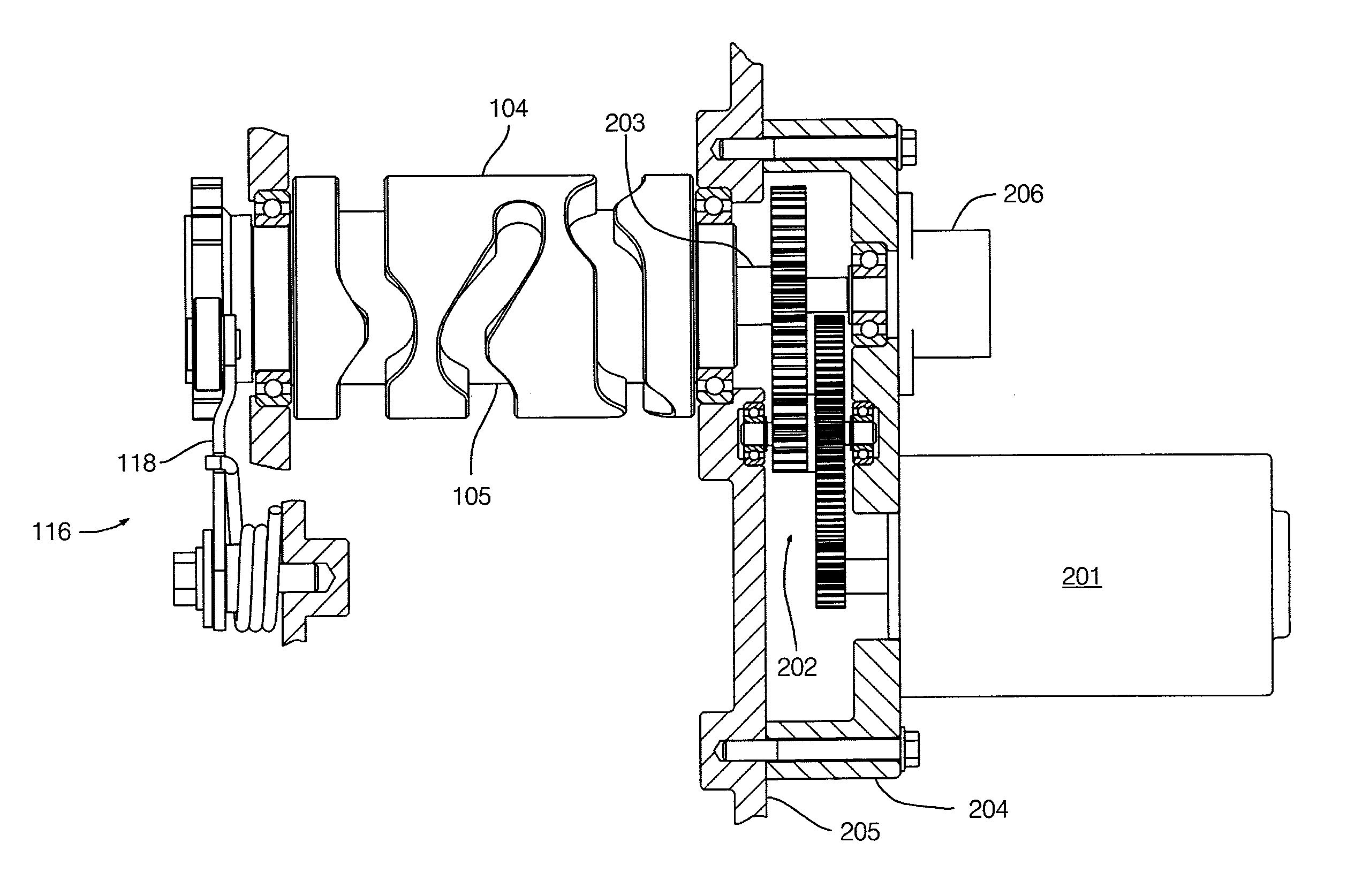
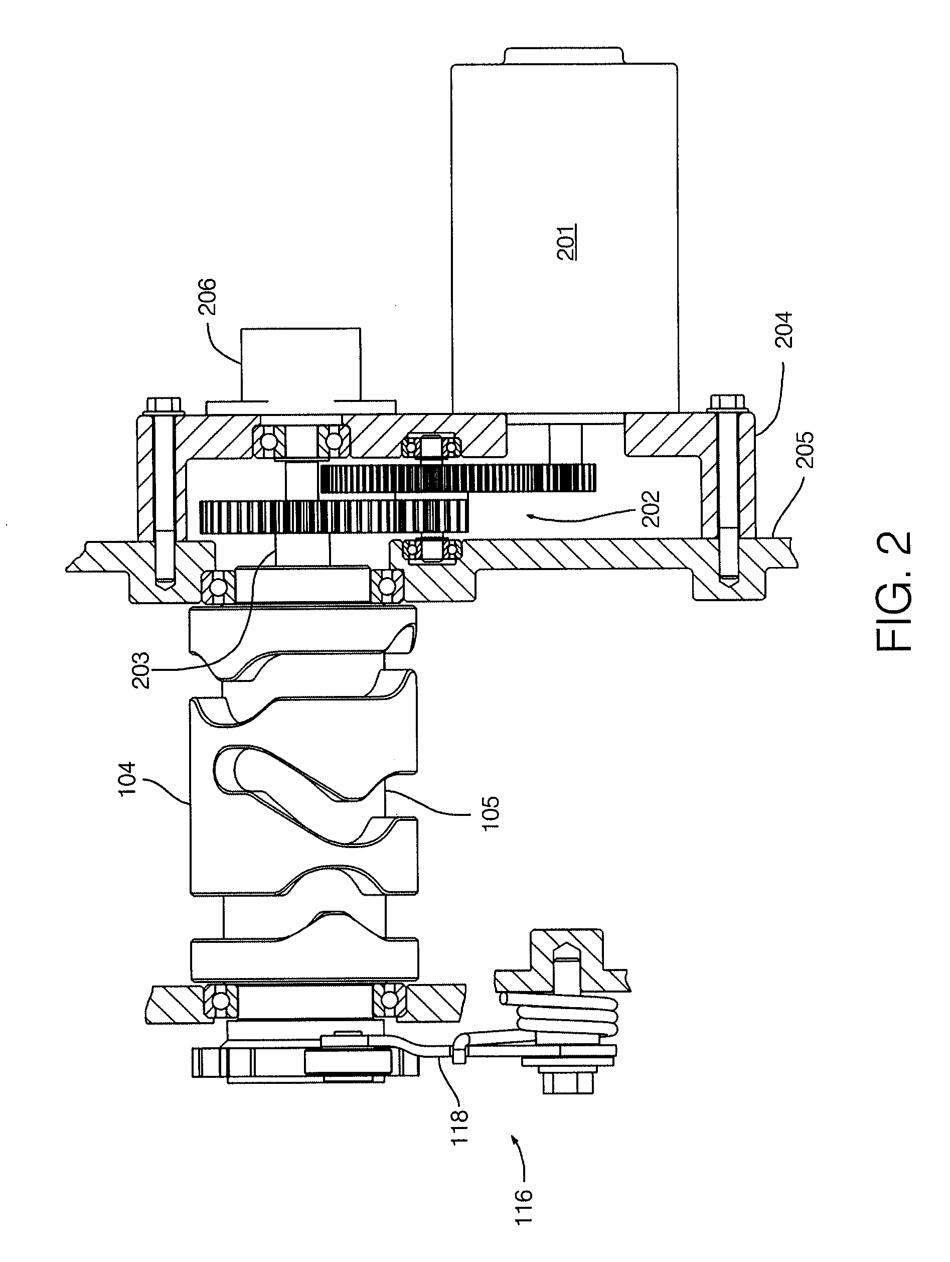
[0031]FIG. 2 shows one embodiment of the invention comprising a control motor 201 driving the selector drum 104. A cam indexer 116 having a series of impressions therein biases the selector drum 104 into a fixed number of gear positions using a biased pawl 118. The control motor 201 may drive the selector shaft 203 through a series of selector shaft gears 202. The control motor 201 may incorporate a position sensor, such as a Hall effect sensor, to determine the position of the control motor 201.

[0032]The selector shaft gears 202 may include spur gears, bevel gears, helical gears and hypoid gears. In a preferred embodiment the selector shaft gears 202 would not include a worm drive arrangement, as worm gear arrangements are typically poor mechanical transmitters of reverse torque, and therefore may not provide good feedback to a torque sensor. Worm gears are helical gears having a helix angle that does not exceed 50 degrees.

[0033]The invention may also comprise a position sensor 206...


PUM


Abstract

An apparatus for controlling a sequential transmission of a vehicle is provided comprising a control motor that drives a selector drum for shifting gears wherein the apparatus measures torque applied to or position of the selector drum and controls the control motor to engage the gears, to accommodate for wear and transient gear interference or jamming.

Description

FIELD OF THE INVENTION[0001]The present invention relates to an apparatus and system for controlling a sequential transmission using a control motor and sensors to shift gears.BACKGROUND OF THE INVENTION[0002]A transmission is used to transmit power from an engine to a drive mechanism. The transmission uses the principle of mechanical advantage to convert the rotational speed, direction, and torque of a driving element into a different rotational speed, direction, and torque of a driven element. Most transmissions use a combination of gears in differing ratios to achieve this speed-torque conversion.[0003]Vehicle transmissions often include more than one set of gear ratios (typically called “gears”) to allow the vehicle to operate in a variety of conditions. When the vehicle is at rest or travelling at a low speed, a gear ratio may be selected to deliver relatively high torque from the engine to the driveline. When the vehicle is travelling at higher speeds, a different ratio may be...

Claims


Application Information

Patent Timeline
Patent Type & Authority Patents(United States)
IPC IPC(8): F16H59/14
CPCF16H61/32F16H63/48F16H63/18Y10T74/2003Y10T74/19274F16H2059/6807F16H63/14
Inventor PICK, DEANDOWAD, THOMAS
Owner PICK DEAN
Why Eureka
Try Eureka