
Voltage source inverter and medium voltage pre-charge circuit therefor

a voltage source inverter and medium voltage technology, applied in the direction of electric variable regulation, process and machine control, instruments, etc., can solve the problems of reducing inrush current by relatively large size and cost of reactors (or resistors)

Inactive Publication Date: 2011-06-21
EATON INTELLIGENT POWER LTD
View PDF7 Cites 17 Cited by
  • Summary
  • Abstract
  • Description
  • Claims
  • Application Information

AI Technical Summary

Benefits of technology

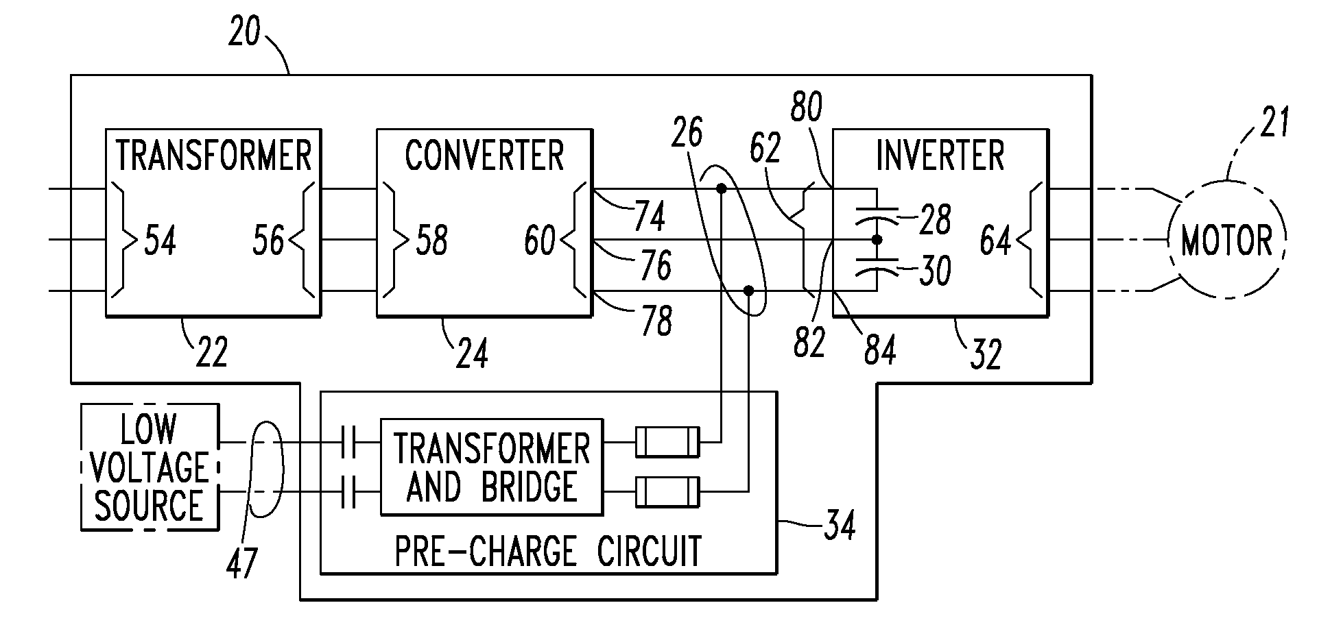
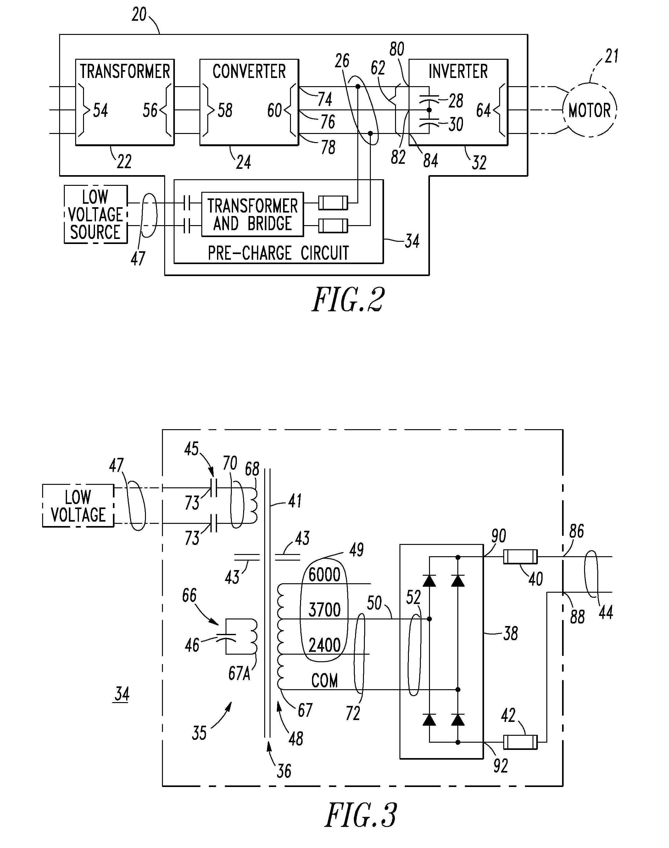
The invention provides a pre-charge circuit for a direct current bus of a voltage source inverter. The circuit includes a ferro-resonant transformer circuit and a medium voltage diode bridge circuit. The ferro-resonant transformer circuit inputs a low voltage and outputs a medium voltage with a constant current source. The medium voltage diode bridge circuit inputs the medium voltage and outputs the constant current source to the direct current bus. This circuit helps to prevent damage to the voltage source inverter during power-up and provides a reliable and constant current source for the direct current bus.

Problems solved by technology

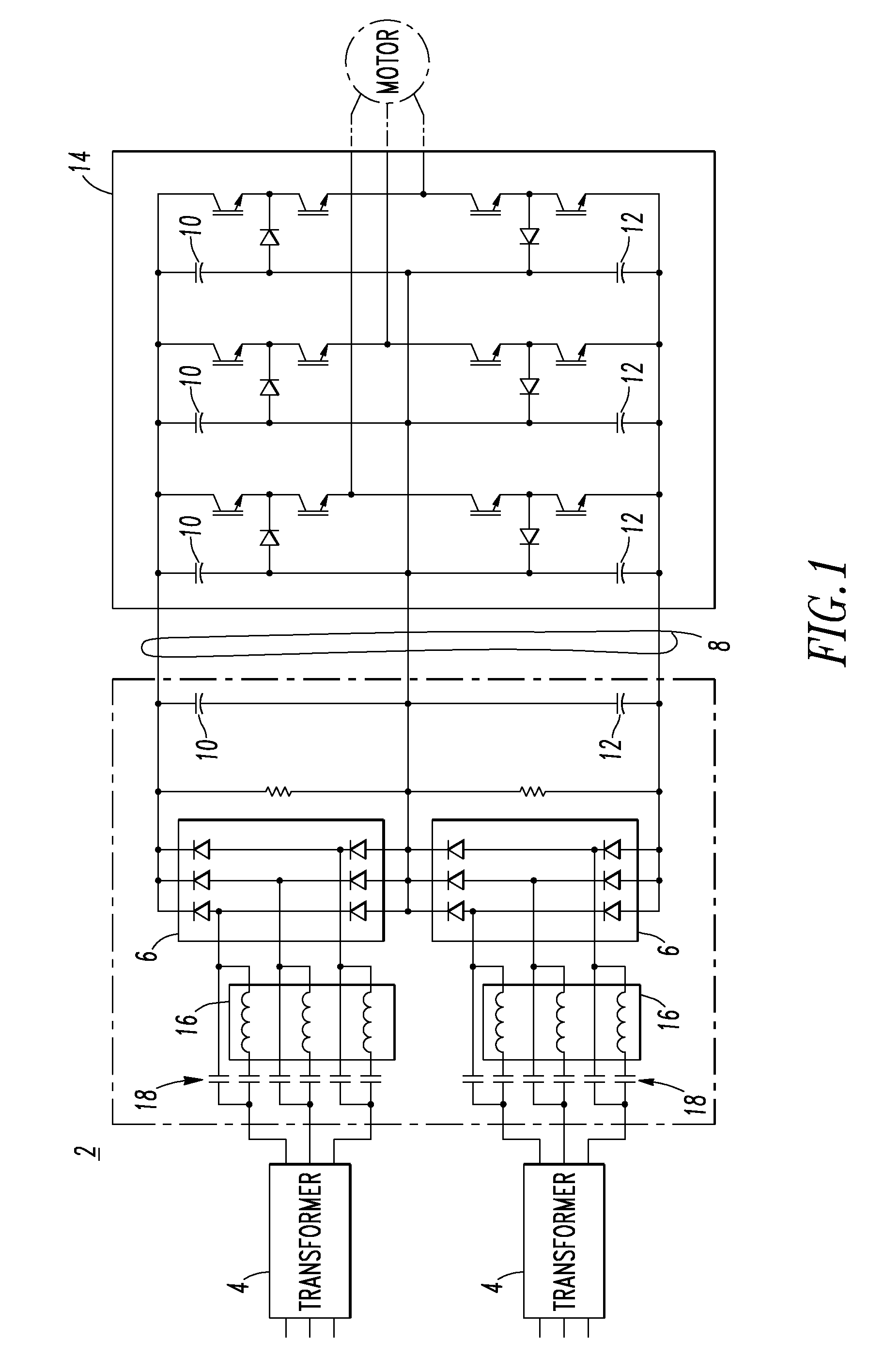
A disadvantage of such known methods of reducing inrush current is the relatively large size and cost of the reactors (or resistors) 16 and the medium voltage rated contactor 18.

Method used


Image

  • Voltage source inverter and medium voltage pre-charge circuit therefor
  • Voltage source inverter and medium voltage pre-charge circuit therefor
  • Voltage source inverter and medium voltage pre-charge circuit therefor

Examples


example

[0033]Compared to a conventional isolation transformer, a ferro-resonant transformer, such as 36, has several main differences: (1) a linear (i.e., non-saturating) AC input (primary) winding, such as 68; (2) a resonant circuit 35 (e.g., capacitor 46 and secondary winding 67A) with a saturable magnetic structure (i.e., the core 41 of the transformer 36); and (3) a magnetic shunt 43 (non-saturating) between the low voltage input AC power 70 and the saturable magnetic structure, which has the resonant circuit 35. This saturable magnetic structure is found in close proximity to the resonant circuit 35. The resonant circuit 35 is tuned very closely to the frequency (e.g., without limitation, 60 Hz) of the input low voltage AC power 47. When excited by that frequency, the resonant circuit 35 builds up enough flux to saturate the (e.g., iron) core 41 of the ferro-resonant transformer 36 every half cycle. In every half cycle of operation, the resonant circuit energy is transferred between t...


PUM


Abstract

A medium voltage adjustable frequency drive includes an input isolation transformer having a three-phase input and a three-phase output, a converter having a three-phase input electrically connected to the three-phase output of the input isolation transformer and an output providing a direct current bus, an inverter having an input electrically connected to the output of the converter and a three-phase output, and a pre-charge circuit. The pre-charge circuit includes a ferro-resonant transformer circuit having a primary winding structured to input a low voltage and a secondary winding structured to output a medium voltage and provide a constant current source. The pre-charge circuit also includes a medium voltage diode bridge having an input receiving the medium voltage from the secondary winding of the ferro-resonant transformer circuit and an output structured to provide the constant current source to the direct current bus.

Description

BACKGROUND OF THE INVENTION[0001]1. Field of the Invention[0002]This invention pertains generally to voltage source inverters and, more particularly, to voltage source inverters such as, for example, medium voltage adjustable frequency drives or adjustable speed drives. The invention also pertains to medium voltage pre-charge circuits for such voltage source inverters.[0003]2. Background Information[0004]A voltage source inverter, such as a medium voltage adjustable frequency drive, powers a motor, such as an induction or synchronous motor, or a generator, with a suitable medium voltage.[0005]Another example of a voltage source inverter is a variable frequency drive (VFD), which controls the rotational speed of an alternating current (AC) electric motor by controlling the frequency of the electrical power supplied to the motor. A VFD is a specific type of adjustable speed drive. VFDs are also known as adjustable frequency drives (AFDs), variable speed drives (VSDs), AC drives, micro...

Claims


Application Information

Patent Timeline
Patent Type & Authority Patents(United States)
IPC IPC(8): H02M7/537H02J3/36G05F1/13
CPCH02M7/062
Inventor GIBBS, IRVING A.STEVENSON, ANDREW C.
Owner EATON INTELLIGENT POWER LTD
Learn More