Quasi Z source inverter

A source inverter and inverter technology, applied in the field of quasi-Z source inverter, to achieve high boost, soft start characteristics, good reliability and efficiency

Inactive Publication Date: 2013-05-22
SOUTHEAST UNIV
View PDF6 Cites 12 Cited by
  • Summary
  • Abstract
  • Description
  • Claims
  • Application Information

AI Technical Summary

Problems solved by technology

[0004] Purpose of the invention: In view of the problems and deficiencies that the conventional inverters in the prior art cannot realize the

Method used


Image

  • Quasi Z source inverter
  • Quasi Z source inverter
  • Quasi Z source inverter

Examples


Embodiment Construction

[0014] Below in conjunction with accompanying drawing and specific embodiment, further illustrate the present invention, should be understood that these embodiments are only for illustrating the present invention and are not intended to limit the scope of the present invention, after having read the present invention, those skilled in the art will understand various aspects of the present invention Modifications in equivalent forms all fall within the scope defined by the appended claims of this application.

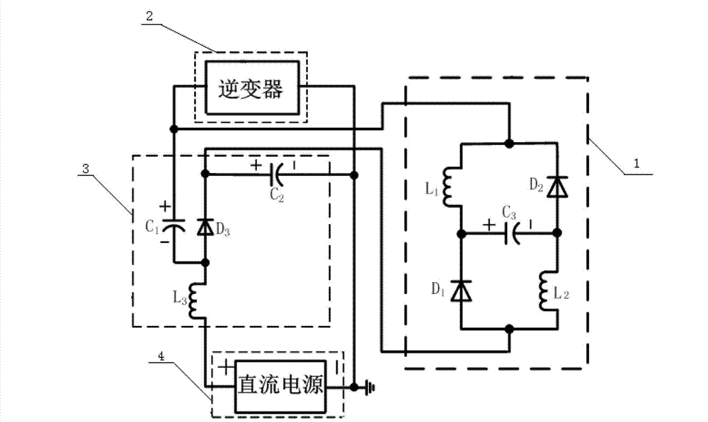
[0015] Such as figure 1 As shown, the present invention is mainly composed of a switch inductor group 1, an inverter 2, an auxiliary circuit 3 and a DC power supply 4, and the switch inductor group 1 includes a first diode D 1 , the second diode D 2 , the first inductance L 1 and the second inductance L 2 and the third electrolytic capacitor C 3 , the first diode D 1 One end and respectively with the first inductance L 1 One end and the third electrolytic capacitor...


PUM


Abstract

The invention discloses a quasi Z source inverter which comprises a direct-current power source, an inverter, a switch inductance set and an auxiliary circuit in mutual connection. The quasi Z source inverter can realize boost-buck of any proportion of voltage on a direct-current side without a DC-DC (direct current) booster circuit before inversion, has good effects in terms of reliability and efficiency, has higher boost-buck times than common impedance network type inverters, is free of impact to an electrolytic capacitor when a system is started, can realize soft start characteristics and has the advantages of high step-up, stability, small size, high efficiency and the like.

Description

technical field [0001] The invention relates to an inverter, in particular to a quasi-Z source inverter. Background technique [0002] With the rapid development of modern high-performance digital processing technology and the maturity of power switching device manufacturing technology, power electronics technology is developing at an unprecedented speed. As one of the core technologies, inverter technology is widely used in industrial production, daily life, military manufacturing, etc. has a wide range of applications. In today's increasingly depleted energy, new energy power generation such as photovoltaic solar energy is becoming the technological commanding heights of competition among countries, and inverter technology is the core of the entire system. The energy efficiency, safety reliability, and operability of the inverter are related to the safe operation and economic benefits of the system. Therefore, the development of high-efficiency, energy-saving, safe, and r...

Claims


Application Information

Patent Timeline
IPC IPC(8): H02M1/36H02M7/44
Inventor 梅军郑建勇邓凯孙博梅飞付广旭
Owner SOUTHEAST UNIV
Why Eureka
Try Eureka