
Series quasi Z source inverter based grid-tied PV control method

A technology of a source inverter and a control method, applied in the field of photovoltaic grid-connected control, can solve problems such as affecting the quality of grid-connected power, complicated programming, and high cost of sensor signal processing circuits.

Inactive Publication Date: 2016-09-07
CHANGZHOU POWER SUPPLY OF JIANGSU ELECTRIC POWER +2
View PDF5 Cites 11 Cited by
  • Summary
  • Abstract
  • Description
  • Claims
  • Application Information

AI Technical Summary

Problems solved by technology

[0008] Option 1 Because the system uses a traditional inverter, there is no direct working state, and the dead time added to the control signal will affect the grid-connected power quality
The voltage vector control based on the dq coordinate system involves trigonometric function transformation, which has a large amount of calculation, poor real-time performance, and complicated programming
[0009] Solution 2: Introducing the Z-source inverter into the photovoltaic grid-connected and reactive power compensation control system can effectively improve the power quality of the system, but the Z-source inverter also mainly adopts the direct current control method of voltage vector orientation. Voltage / input current and DC bus voltage, many sensors and their signal processing circuits bring high cost and complexity
Moreover, photovoltaic grid-connected inverters respond quickly and are difficult to participate in grid regulation, so they cannot provide the necessary voltage and frequency support to the distribution network like a synchronous generator, and lack a "synchronization" mechanism with the distribution network

Method used


Image

  • Series quasi Z source inverter based grid-tied PV control method
  • Series quasi Z source inverter based grid-tied PV control method
  • Series quasi Z source inverter based grid-tied PV control method

Examples


Embodiment Construction

[0062] The present invention will be further described below in conjunction with the accompanying drawings. The following examples are only used to illustrate the technical solution of the present invention more clearly, but not to limit the protection scope of the present invention.

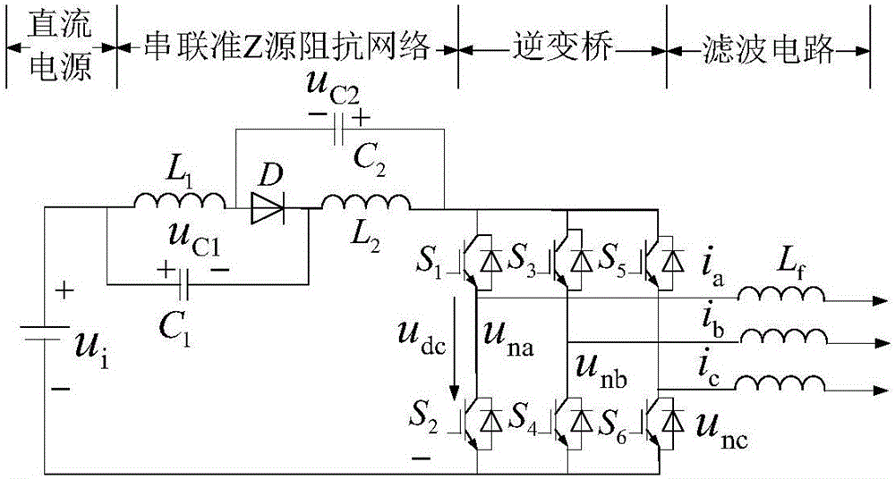
[0063] Such as figure 2 As shown, the present invention first designs a series quasi-Z source inverter topology, based on the topology conversion circuit of the series quasi-Z source impedance network, the DC input power u i , series quasi-Z source impedance network, three-phase inverter bridge (S 1 ~S 6 ) and filter circuit L f It consists of four parts.

[0064] The three-phase series quasi-Z source inverter has a total of 15 allowable switching states as shown in Table 1. When the bus voltage u dc When applied on both sides of the three-phase load, the three-phase series quasi-Z source inverter has the same six non-zero vectors as the traditional voltage source inverter, that is, the e...


PUM


Abstract

The present invention discloses a series quasi Z source inverter based grid-tied PV control method. A PV battery inverter system is seen as a virtual synchronous generator, and an integral of an output voltage of a series quasi Z source inverter is taken as a virtual motor magnetic chain. An outer ring is controlled by using a power ring, so that active power transmission and reactive power compensation are realized. An inner ring is a current ring, so that current rapid tracking is realized. PI modulation is performed on the current inner ring, so as to generate a modulated wave signal. Three times of harmonic wave modulation is performed on a modulated signal obtained at a PV side and the modulated wave signal. On and off of an inverter bridge are controlled, so as to realize power adjustment of the grid-tied PV system. According to the method, a virtual synchronous generator quasi direct power control policy is adopted for controlling the system, the virtual magnetic chain directly orients, an alternating current voltage sensor is omitted, system reliability is improved, device cost is saved, quasi direct power control can directly control active power and reactive power of the grid-tied inverter, and the system has the advantages of simple structure and good dynamic response performance.

Description

technical field [0001] The invention relates to a photovoltaic grid-connected control method based on a series quasi-Z source inverter, and belongs to the technical field of photovoltaic grid-connected control. Background technique [0002] In the photovoltaic power generation system, the main problem is how to improve the working efficiency of solar cells. The power electronic conversion in the system is the key to solve this problem. On the one hand, the power conversion link must realize the maximum power point tracking of the solar cell, and on the other hand, it must realize the sine wave output and phase control of the inverter circuit. For two-stage or multi-stage photovoltaic grid-connected systems, these two functions are generally realized in two transformation links. For example, first implement maximum power point tracking (MPPT) control in a DC / DC link, and then implement sinusoidal current output and phase control in a DC / AC link, which is conducive to the rea...

Claims


Application Information

Patent Timeline
IPC IPC(8): H02J3/38H02J3/18
CPCH02J3/1821H02J3/383Y02E10/56Y02E40/30
Inventor 王伟冯炜姬丽雯汪立俊杜炜陈磊周光刘刚王彦隽
Owner CHANGZHOU POWER SUPPLY OF JIANGSU ELECTRIC POWER
Learn More