Flare apparatus

a flare apparatus and flare technology, applied in the field of flare apparatuses, can solve the problems of difficult or impractical to muffle the noise of the lower steam can be muffled, and the noise of the upper steam is difficult or impractical to muffl

Active Publication Date: 2011-06-28
JOHN ZINK CO LLC
View PDF85 Cites 14 Cited by
  • Summary
  • Abstract
  • Description
  • Claims
  • Application Information

AI Technical Summary

Benefits of technology

[0028]The flare apparatus of the current invention provides a number of advantages over the prior art flare apparatus, one configuration of which is schematically shown in FIGS. 16 and 17. Prior art flare tip 116 has an outer cylinder 118 into which combustible gas is communicated. Steam is injected into outer cylinder 118 through a center steam injector 120. A plurality of lower steam injectors 122 direct steam into a plurality of lower steam tubes 124. Combustible gas moves in outer cylinder 118 between lower steam tubes 124. Upper steam is injected through upper steam injectors 126. Upper steam is necessary to maintain perimeter control and to provide an efficient air / steam and combustible gas mixture above outer cylinder 118 for smokeless burning.

Problems solved by technology

However, such flare apparatus may create an excessive amount of noise.
The noise from the lower steam can be muffled, while the noise from the upper steam is difficult or impractical to muffle due to its vicinity to the flare flame.
A muffler for the lower steam not only adds to the costs, but also increases the wind load of the flare stack, resulting in increased flare stack costs.

Method used


Image

  • Flare apparatus
  • Flare apparatus
  • Flare apparatus

Examples


Embodiment Construction

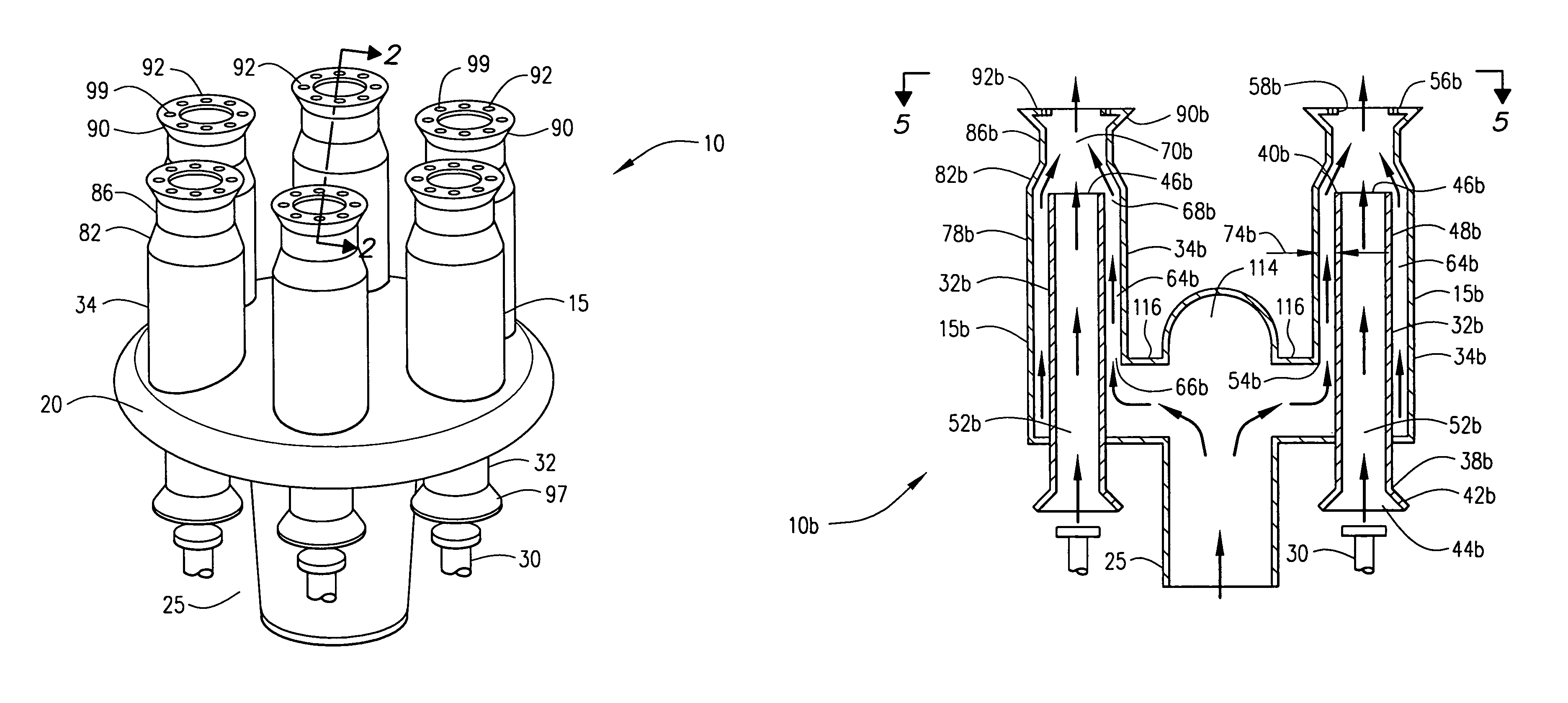
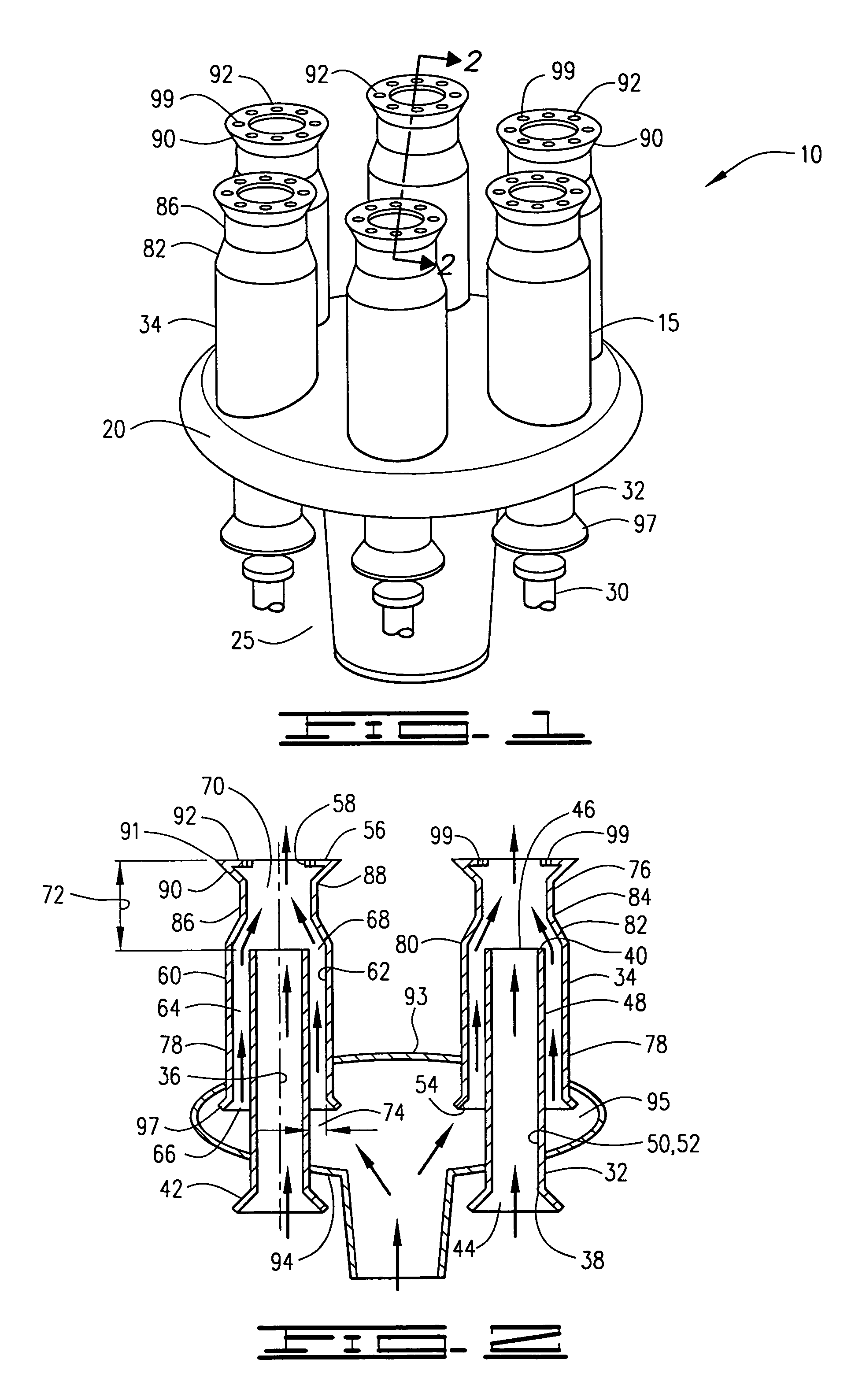
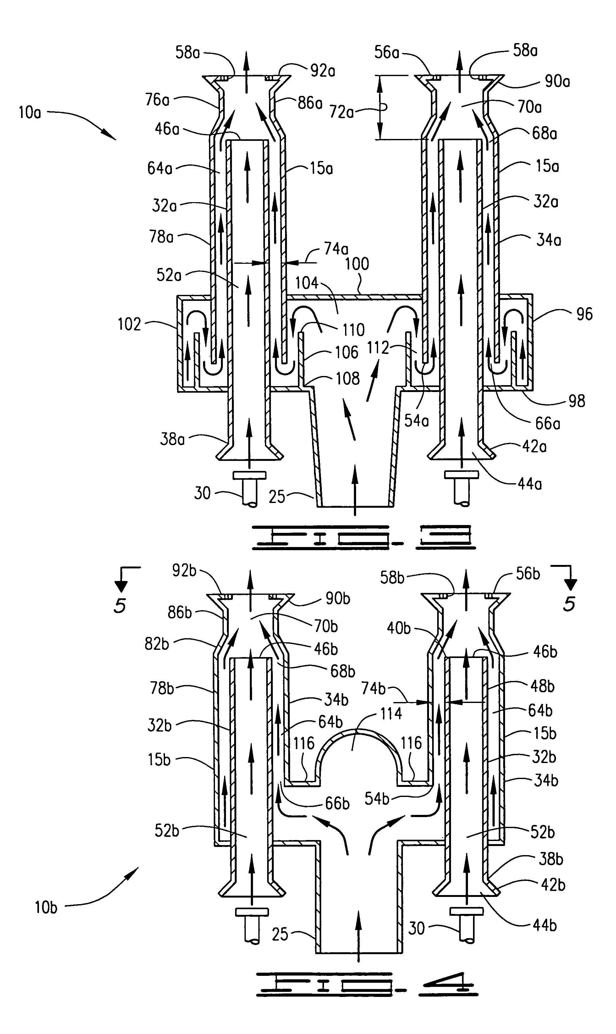
[0019]Referring now to the drawings, a flare apparatus, which may be referred to as a flare tip 10 is shown. Flare apparatus 10 is adapted to be used at the top of a flare stack, which as known in the art will communicate a combustible gas from a combustible gas source to flare apparatus 10. The combustible gas may be a waste gas from a refinery, processing plant, chemical plant, production site, LNG production plant, or other source. The gas may comprise, for example, propane, propylene, natural gas, hydrogen, carbon monoxide, ethylene or other gas. Flare apparatus 10 includes a plurality of flare tip units, or flare structures 15 for receiving the combustible gas from a single gas supply 20, which in FIG. 1 is a plenum 20. A gas pipe 25 connectable to the flare stack (not shown) will deliver combustible gas from the combustible gas source to the plenum 20.

[0020]Flare apparatus 10 may include a plurality of steam injectors 30 for providing a motive force to move air through each fl...


PUM


Abstract

A flare apparatus for burning combustible gases. A flare tip unit comprises an inner member and an outer member defining an annulus therebetween. The annulus defines an annular gas passage through which combustible gas passes. Air moved by a motive force, preferably steam, passes through the inner member and a steam / air mixture exits an outlet of the inner member. The combustible gas and an air / steam mixture mixes in a premix zone between the inner member outlet and the exit opening of the outer member. The combustible gas / air / steam mixture is ignited for burning in the atmosphere above the exit opening. The flare apparatus may include a plurality of flare tip units.

Description

BACKGROUND OF THE INVENTION[0001]The present invention relates to an improved flare apparatus and more specifically to an efficient steam-assisted flare apparatus.[0002]Flare apparatus for burning and disposing of combustible gases are well known. Flare apparatus are commonly mounted on flare stacks and are located at production, refining, processing plants and the like for disposing of flammable waste gases or other flammable gas streams which are diverted for any reason including but not limited to venting, shut-downs, upsets and / or emergencies. Flare apparatus are extremely important in the event of plant emergencies such as fire or power failure and a properly operating flare system is a critical component to prevent plant disruption in any of the above-mentioned or other circumstances.[0003]It is generally desirable that the flammable gas be burned without producing smoke and typically such smokeless or substantially smokeless burning is mandatory. One method for accomplishing ...

Claims


Application Information

Patent Timeline
Patent Type & Authority Patents(United States)
IPC IPC(8): F23G7/08F23D14/62
CPCF23L7/005F23G7/085F23D14/02F23D14/58
Inventor HONG, JIANHUIWILKINS, JAMESWHITE, JEFF WILLIAMPOE, ROGER L.
Owner JOHN ZINK CO LLC
Why Eureka
Try Eureka