Method for vaporizing liquid material capable of vaporizing liquid material at low temperature and vaporizer using the same

a liquid material and low temperature technology, applied in the field of vaporizers, can solve the problems of thermal decomposition products and polymers, liquid material would be not only vaporized but also chemically modified, accumulate in the vaporizer, etc., and achieve high thermal decomposability, high vaporization efficiency, and high vaporization efficiency

Active Publication Date: 2011-07-12
LINTEC CO LTD
View PDF14 Cites 7 Cited by
  • Summary
  • Abstract
  • Description
  • Claims
  • Application Information

AI Technical Summary

Benefits of technology

[0009]The present invention is intended to provide the vaporizer capable of decreasing the temperature of vaporization owing to high vaporization efficiency thereof, preventing accumulation of thermal decomposition products and polymers in the vaporizer and blocking of the passages even for the liquid material with high thermal decomposability, and vaporizing a large amount of the liquid material.
[0026]According to the six aspect, the liquid material (LM) fed to the primary filter (80) is not affected by a variation in the flowing air within the vaporizing chamber (60). Accordingly, change in a thickness of a liquid film (114) formed on the surface of the primary filter (80) can be decreased, and thus a vaporizer (110) can offer stable vaporization performance.

Problems solved by technology

Although many vaporizers for vaporizing the liquid material have been developed and used, these vaporizers have the following problems.
However, if the temperature of vaporization is excessively increased, the liquid material would be not only vaporized but also chemically modified due to the liquid material itself being thermally decomposed.
Thus it results in the problem that thermal decomposition products and polymers, accumulate in the vaporizer, blocking passages for the liquid material, for example.

Method used


Image

  • Method for vaporizing liquid material capable of vaporizing liquid material at low temperature and vaporizer using the same
  • Method for vaporizing liquid material capable of vaporizing liquid material at low temperature and vaporizer using the same
  • Method for vaporizing liquid material capable of vaporizing liquid material at low temperature and vaporizer using the same

Examples


first embodiment

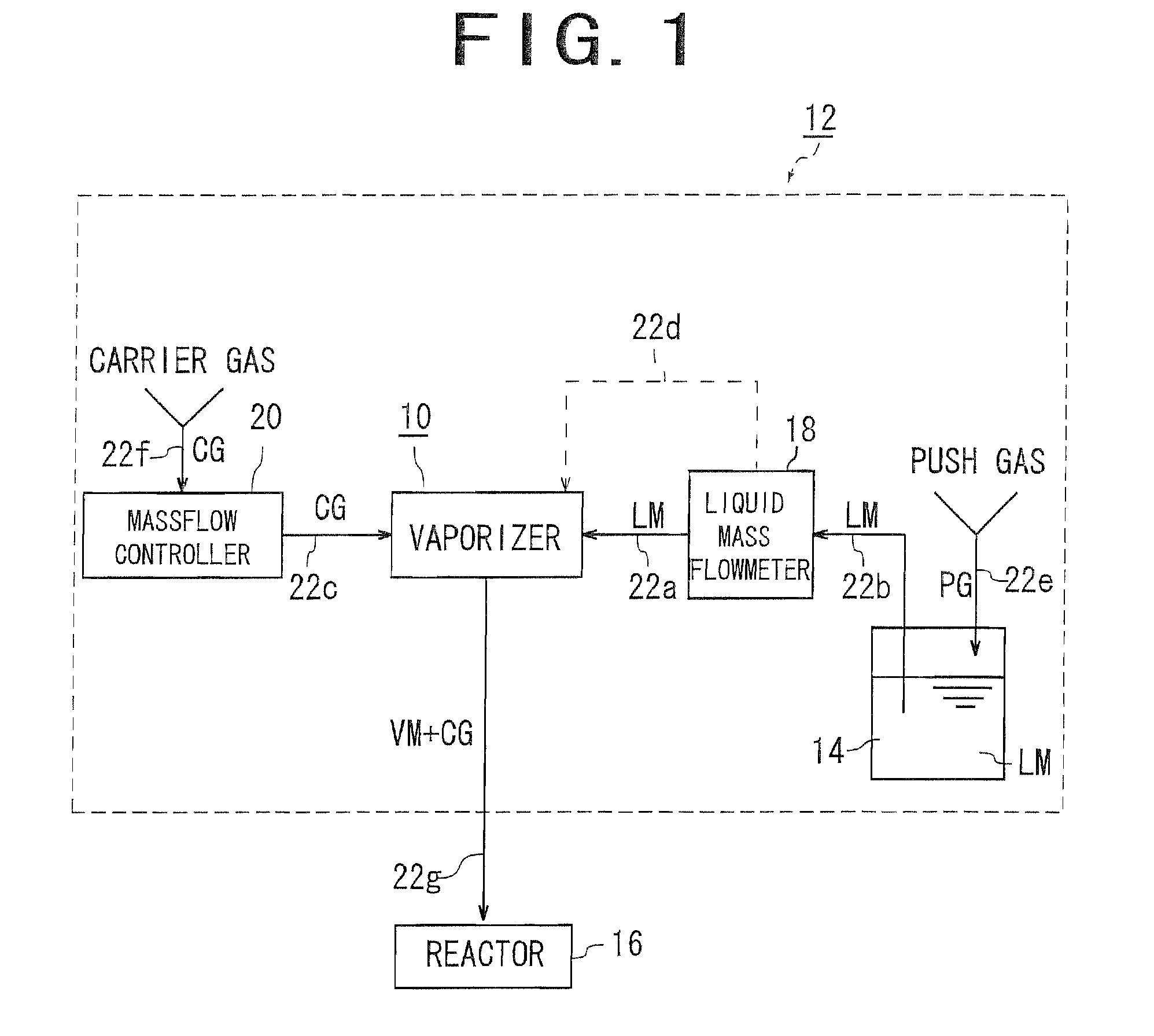
[0049]FIG. 1 shows an example of a vaporized liquid material supplying apparatus (12) having the vaporizer (10) according to the present invention incorporated therein. In this regard, the vaporized liquid material supplying apparatus (12) is for vaporizing a liquid material (LM) supplied from a material tank (14) to provide a vaporized material (VM). And the vaporized liquid material supplying apparatus (12) is for conveying the vaporized material (VM) by a carrier gas (CG) to supply it to a reactor (16), such as a CVD apparatus. In addition, the vaporized liquid material supplying apparatus (12) includes the vaporizer (10), the material tank (14), a liquid mass flowmeter (18), and a massflow controller (20), or the like, which are connected to each other via liquid material supply tubes (22a), (22b), and a carrier gas supply tube (22c). The vaporizer (10) and the liquid mass flowmeter (18) are connected to each other via a control line (22d).

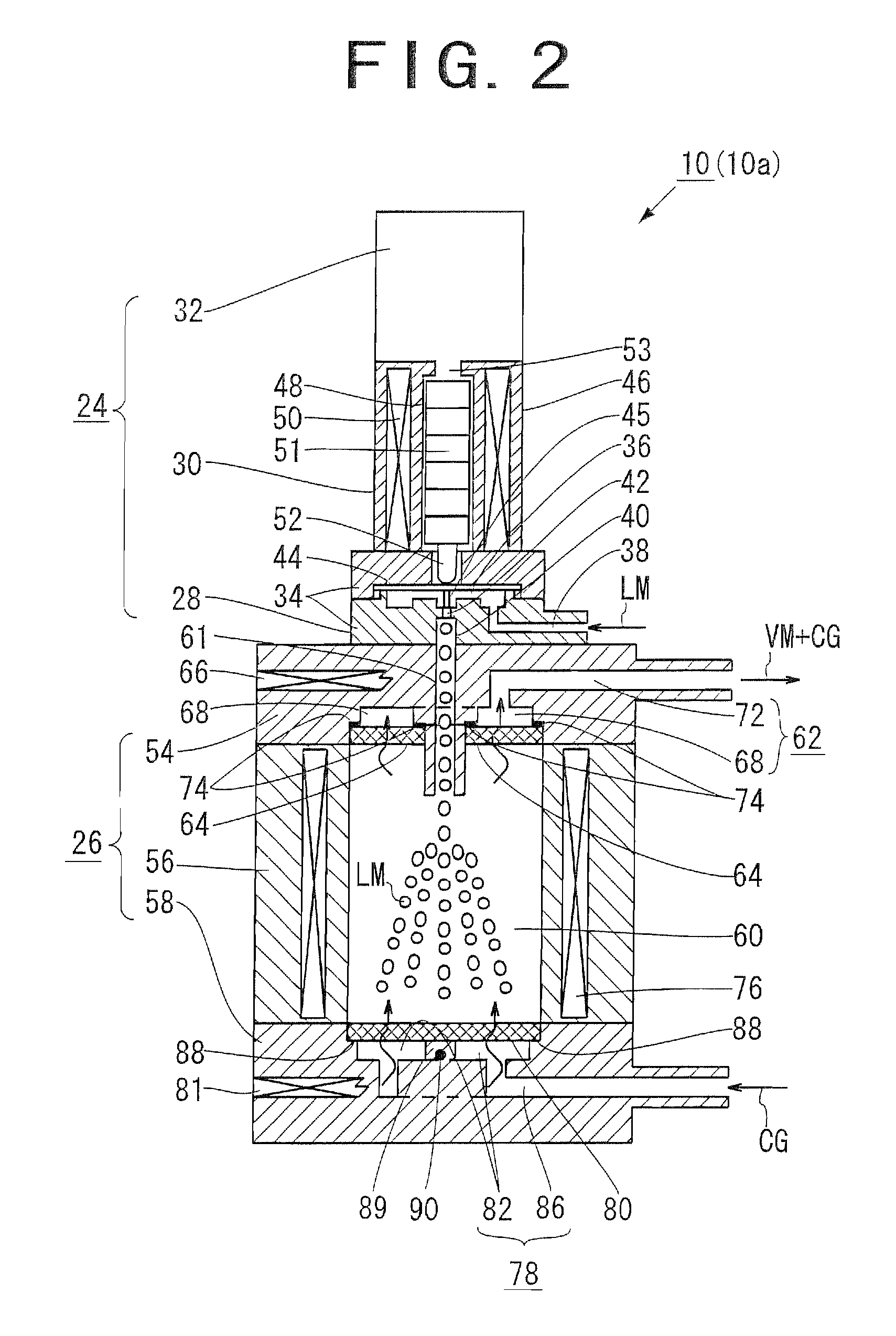
[0050]A vaporizer (10a) adopting the pr...

second embodiment

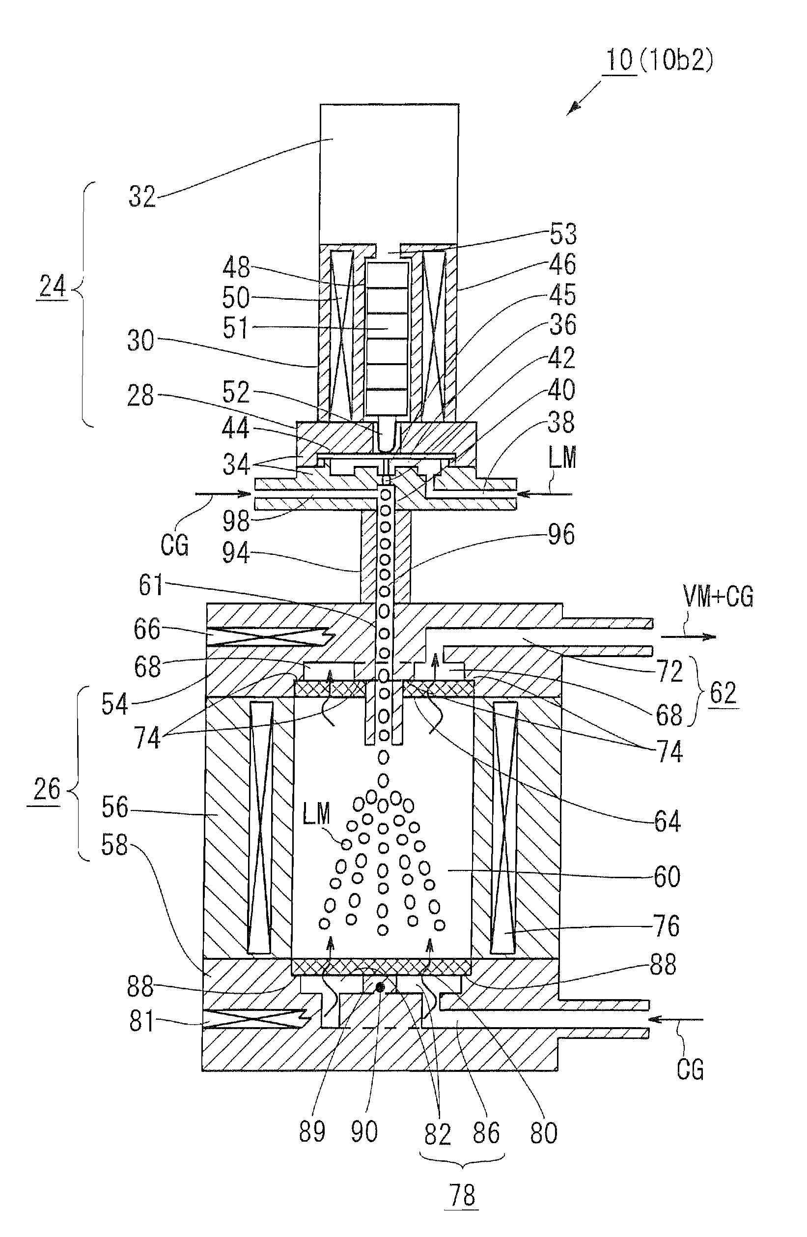
[0081]An embodiment suitable for the case where the temperature must be set up higher in order to vaporize the liquid material with lower vapor pressure and being more difficult to vaporize (hereinbelow, referred to as“vaporization-resistant liquid material”) as compared with the liquid material (LM) used in the first embodiment is described (FIG. 6). A vaporizer (10b1) for the vaporization-resistant liquid material generally includes the liquid material supply portion (24) and the vaporizing portion (26), as with the vaporizer (10a) according to the first embodiment, and its configuration as an apparatus is also substantially the same. Then, only differences with the first embodiment are described as follows.

[0082]In the vaporizer (10b1) for the vaporization-resistant liquid material, the liquid material supply portion (24) and the vaporizing portion (26) are isolated from each other, and a connecting tube for heat isolation (94) is arranged therebetween.

[0083]The connecting tube f...

third embodiment

[0088]A vaporizer (10c) according to this embodiment includes a preheating filter (102) added to the lower block (58) of the vaporizer (10c) according to the first embodiment.

[0089]As shown in FIG. 8, there is provided another space (104) between the recess (82) and the passage (86) in the carrier gas guiding passage (78) of the vaporizer (10c). The recess (82) and the space (104) are connected to each other via an orifice (106). And the passage (86) is connected to the space (104). Consequently, the carrier gas (CG), guided into the passage (86), is guided into the recess (82) via the space (104) and then fed to the vaporizing chamber (60) through the primary filter (80).

[0090]A step is provided on the side of the space (104). And the upper end portion of the space (104) is formed wider than the lower section of the space (104). This step forms a joint portion (108) where an inner surface of the space (104) in on a surface of the preheating filter (102) when the preheating filter (...


PUM

PropertyMeasurementUnit
inner diameteraaaaaaaaaa
temperatureaaaaaaaaaa
vapor pressureaaaaaaaaaa

Abstract

A vaporizer is provided with a vaporizing chamber heated by heaters; a primary filter positioned in a bottom end portion of the vaporizing chamber and heated by the heater; a liquid material supply portion for dropping down a flow-controlled liquid material from upper portion of the vaporizing chamber toward the primary filter; a carrier gas guiding passage for guiding a carrier gas into the underside of the primary filter; and a material delivering passage for discharging a mixed gas including the carrier gas and a vaporized liquid material from the top of the vaporizing chamber. The liquid material dropped down onto the primary filter is partially vaporized, while the rest thereof is atomized by being subjected to bubbling effect provided by the carrier gas flowing from underneath.

Description

BACKGROUND OF THE INVENTION[0001]1. Field of the Invention[0002]The present invention relates to a vaporizer capable of efficiently vaporizing a liquid material for thin film production supplied to a CVD apparatus, at low temperature.[0003]2. Description of the Related Art[0004]In a process of producing a semiconductor device, chemical vapor deposition apparatus (CVD apparatus) deposit variety of thin films on a wafer.[0005]In recent years, in the CVD apparatus, liquid compounds, such as liquid organic compounds and organic metal solutions, have been used as a liquid material for thin film production. A vaporizer for the liquid material is indispensably preceded by the CVD apparatus, because it is necessary to supply a vaporized liquid material to the CVD apparatus to deposit the thin film on the wafer in the CVD apparatus.[0006]Typical means for vaporizing the liquid material includes a method of vaporizing the liquid material in the vaporizer with heat supplied by a heater or the ...

Claims


Application Information

Patent Timeline
Patent Type & Authority Patents(United States)
IPC IPC(8): B01F3/04
CPCC23C16/4486Y10S261/65Y10T137/0391C23C16/00C23C16/448
Inventor ONO, HIROFUMI
Owner LINTEC CO LTD
Why Eureka
Try Eureka