Work handling apparatus

a technology for handling apparatuses and work, applied in the direction of lighting and heating apparatuses, charge manipulation, furnaces, etc., can solve the problems of difficult productivity improvement, achieve efficient production, improve productivity, and operate and transfer efficiently

Inactive Publication Date: 2011-07-12
HIRATA & CO LTD
View PDF13 Cites 10 Cited by
  • Summary
  • Abstract
  • Description
  • Claims
  • Application Information

AI Technical Summary

Benefits of technology

[0008]In view of such circumstances, it is an object of the present invention to provide a work handling apparatus which is capable of performing efficiently various operations including processing such as coating, heat processing, chemical processing and cleaning, inspection, measurement, machining and assembly for works including electronic parts such as a semiconductor chip or substrate, or machine parts while achieving simple structure, aggregation of respective mechanisms, downsizing of entirety of the apparatus, saving of an installation area and reduction of time required for transferring works, so that the productivity is improved.

Problems solved by technology

However, the transfer hands in this apparatus transfer the works two-dimensionally within a vertical plane and do not transfer the works two-dimensionally within a horizontal plane.
However, in this apparatus, the loading mechanism travels only within a left side area for transferring the works and the unloading mechanism travels only within a right side area for transferring the works.
That is, since the loading mechanism and the unloading mechanism are formed so as to travel their own areas (the left side area and the right side area) arranged at a distance to a certain degree in the direction of the horizontal plane in order to avoid mutual interference, it is difficult to arrange the loading mechanism and the unloading mechanism intensively near the center, and hence a relatively large space is necessary for installing this apparatus in a semiconductor manufacturing line or the like.
Because of inevitable upsizing, the traveling distance for transferring the work is elongated as well, whereby the time period required for conducting a predetermined inspection after the work is loaded in the inspection area and unloading the works having completed the inspection to the predetermined area again is elongated, so that improvement of the productivity is difficult.

Method used


Image

  • Work handling apparatus
  • Work handling apparatus
  • Work handling apparatus

Examples


Embodiment Construction

[0067]Referring now to the attached drawings, the present invention will be described.

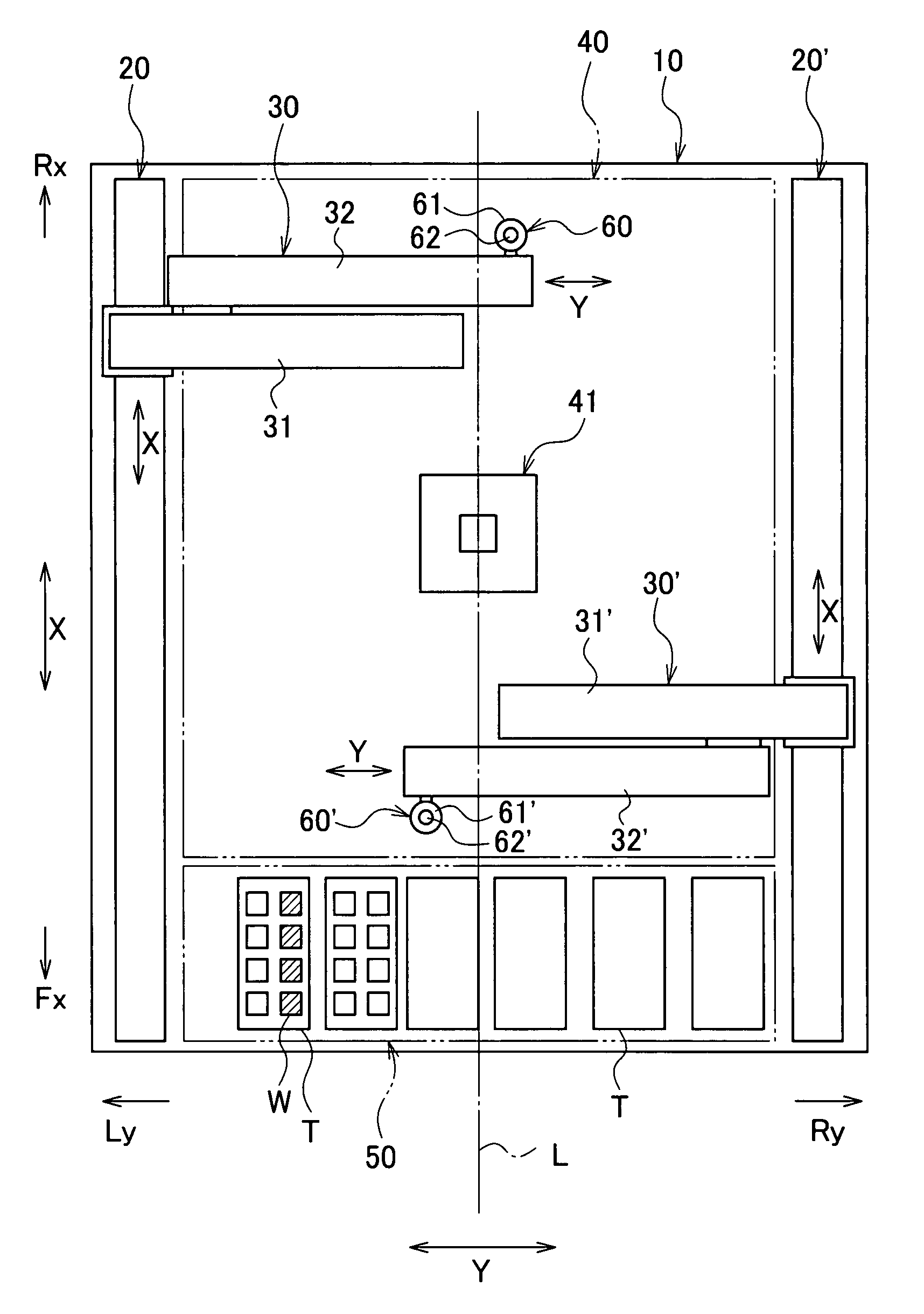
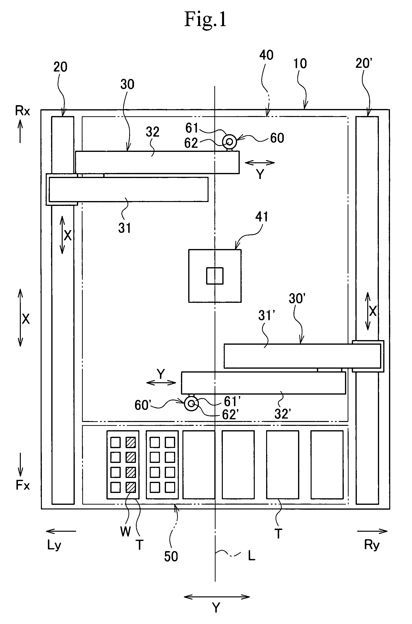
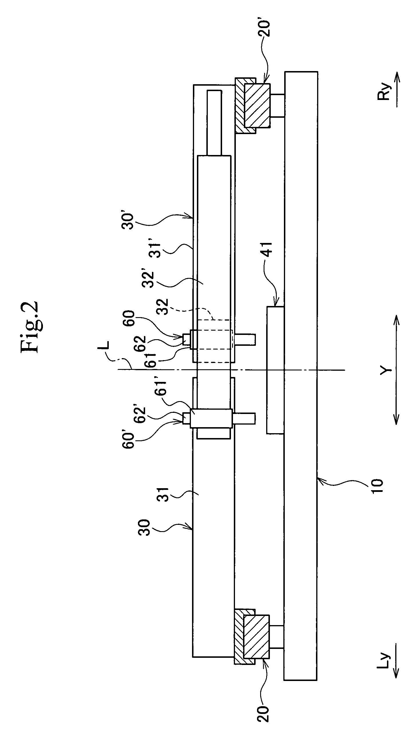
[0068]As shown in FIG. 1 to FIG. 4, a work handling apparatus includes a substantially rectangular base 10, a pair of traveling guides 20, 20′ provided so as to extend in a front-and-rear direction X at a left side Ly and a right side Ry on the base 10, a pair of direct-acting arms 30, 30′ provided so as to travel on the respective traveling guides 20, 20′ independently, an operation spot 41 arranged substantially at the center (an area passing through a centerline L) in an operation area 40 sandwiched between the pair of traveling guides 20, 20′, a work storage area 50 arranged in the front Fx of the base 10 adjacently to the operation area 40, and work tools 60, 60′ mounted respectively on the pair of direct-acting arms 30, 30′.

[0069]The pair of traveling guides 20, 20′ serve to guide the direct-acting arms 30, 30′ respectively in the front-and-rear direction X independently. Therefore, the trave...


PUM


Abstract

A work handling apparatus includes a pair of traveling guides (20, 20′) provided so as to extend in a front-and-rear direction X at right and left sides, and a pair of direct-acting arms (30, 30′) provided so as to travel independently on the pair of traveling guides. The direct-acting arms are extendable from contracted positions, at which the arms oppose each other and avoid mutual interference in a right-and-left direction Y, to extended positions at which the arms overlap with each other. An operation spot (41) is arranged in an operation area (40) sandwiched between the pair of traveling guides for performing a predetermined operation to a work. Also, work tools (60, 60′) are attached to the pair of direct-acting arms (30, 30′), respectively, for transferring the work between a work storage area (50) and the operation spot (41) or performing an operation after transfer.

Description

BACKGROUND OF THE INVENTION[0001]1. Technical Field[0002]The present invention relates to a work handling apparatus for holding, transferring and positioning works when performing various operations including processing such as coating, heat processing, chemical processing and cleaning, inspection, measurement, machining and assembly for the works including electronic parts such as a semiconductor chip or substrate, or machine parts.[0003]2. Description of the Related Art[0004]As a known handling apparatus in the related art for loading and unloading works such as semiconductor chips with respect to an inspection area, for example, there is an apparatus including two transfer channels for transferring a work, two transfer hands being capable of adsorbing the work and reciprocating in a lateral horizontal direction (right-and-left direction) orthogonal to a transfer direction of the two transfer channels and the vertical direction, and inspection sockets arranged at midsections of th...

Claims


Application Information

Patent Timeline
Patent Type & Authority Patents(United States)
IPC IPC(8): B65H5/00
CPCB23Q7/045Y10S414/14
Inventor HIRATA, YASUNARI
Owner HIRATA & CO LTD
Why Eureka
Try Eureka