Error correction encoding apparatus and error correction encoding method used therein

a technology of error correction encoding and encoding method, which is applied in the direction of coding, code conversion, digital transmission, etc., can solve the problems of difficult to evaluate the performance of error-rate characteristics (the obtained coding gain) in an area with low error probability, and the optimum precision is large, so as to achieve the effect of simple apparatus structur

Active Publication Date: 2011-07-12
NEC CORP
View PDF10 Cites 7 Cited by
  • Summary
  • Abstract
  • Description
  • Claims
  • Application Information

AI Technical Summary

Benefits of technology

[0032]In the present invention, by having the configuration and operation described below, the apparatus structure can be made simple, decoding with a close-to-optimum precision can be achieved using an iterative decoding, and evaluation of the characteristic of an error floor area can be performed using a simple mathematical expression without using any computer experiments.

Problems solved by technology

The amount of calculation required for the encoding method (the method for calculating a redundant bit sequence from an information bit sequence) is large, and it is difficult to evaluate the performance of the error-rate characteristics (the obtained coding gain) in an area where the error probability is low, particularly an error floor area.
However, in the cyclic codes or the convolutional codes having a long constraint length, the amount of calculation required for soft-decision decoding that performs decoding with a close-to-optimum precision is very large, offering a problem, and sufficient coding gain cannot obtained, compared with the low-density parity-check codes in which decoding can easily be performed with a close-to-optimum precision using an iterative decoding unit utilizing the aforementioned sum-product algorithm, which is courted as a problem.
As relatively simple codes that can be decoded with a close-to-optimum precision using an iterative decoding and used for an encoding apparatus, turbo codes (for instance, refer to Patent Document 2) are known, however, the turbo codes have low code rates (the ratio between the lengths of the information bit string and the code bit string), therefore they are not suitable for a system that requires a high code rate.

Method used


Image

  • Error correction encoding apparatus and error correction encoding method used therein
  • Error correction encoding apparatus and error correction encoding method used therein
  • Error correction encoding apparatus and error correction encoding method used therein

Examples


Embodiment Construction

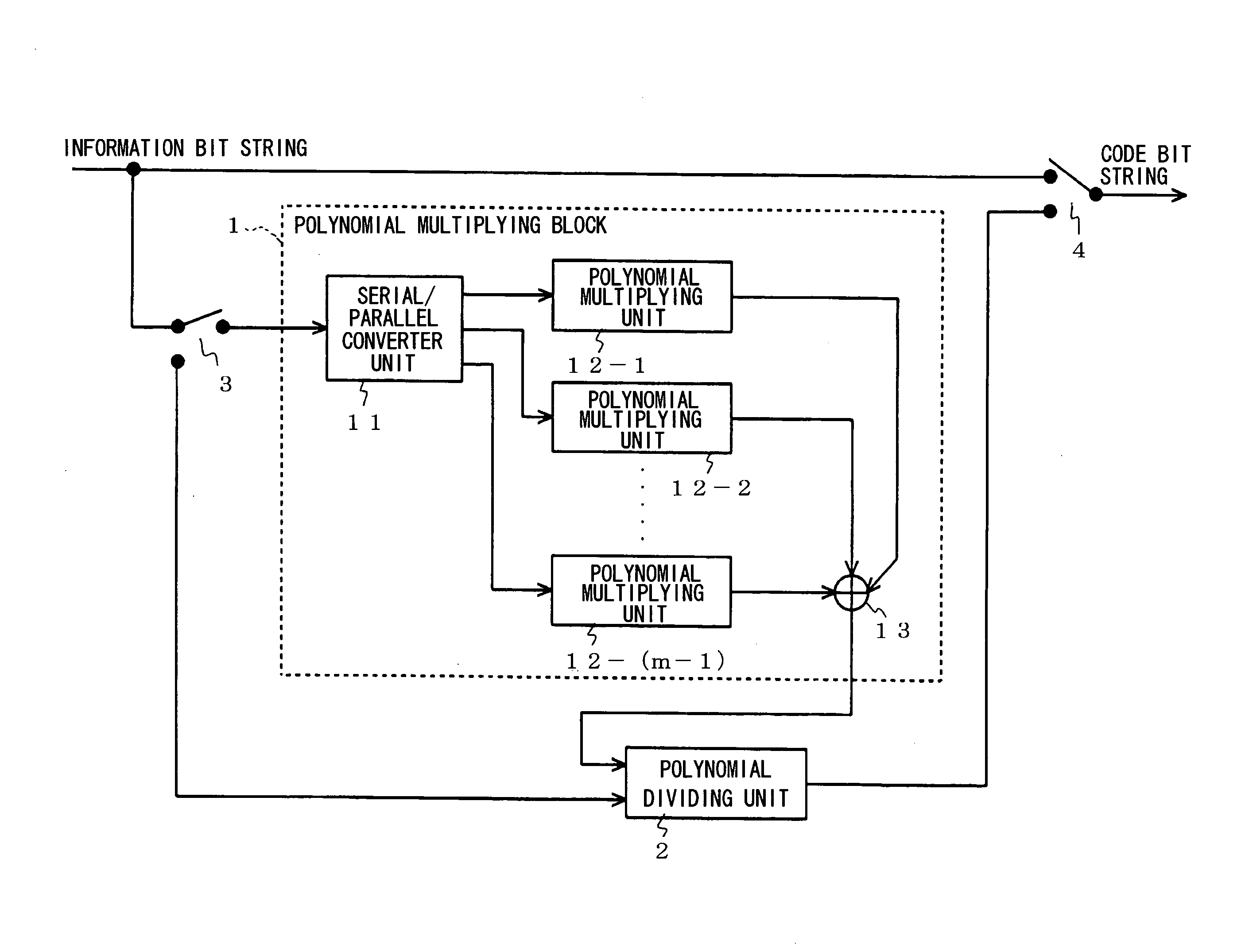
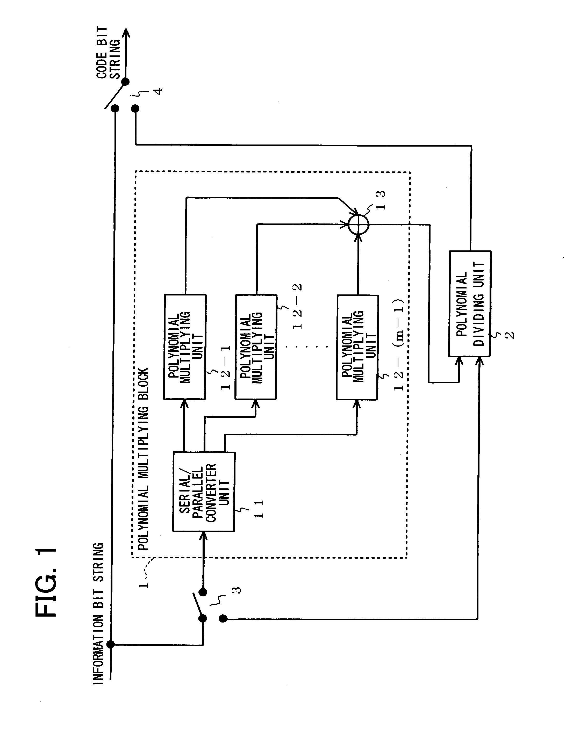
[0049]Next, examples of the present invention will be described with reference to the drawings. FIG. 1 is a block diagram showing the configuration of an error correction encoding apparatus according to an example of the present invention. In FIG. 1, the error correction encoding apparatus according to an example of the present invention is formed by a polynomial multiplying block 1 comprising a serial / parallel (S / P) converter unit 11, an m−1 number of (n−1)-th-order polynomial multiplying units 12-1 to 12-(m−1), and an adder unit 13, a r-th-order polynomial dividing unit 2, and switches 3 and 4, and is an apparatus that converts an information bit string of (nm-r) bits into a code bit string of nm bits (where m and n represent integers equal to or greater than two and r represents an integer from 1 to n, inclusive).

[0050]As described later, the polynomial multiplying block 1 is configured as shown in FIG. 4, however, in order to simplify the explanation, we will assume that the pol...


PUM


Abstract

An error correction encoding apparatus wherein the apparatus structure is simple; an iterative decoding is used to achieve a decoding with a close-to-optimum precision; and a simple mathematical expression is used to perform an evaluation of the characteristic of an error floor area without using any computer experiments. In a polynomial multiplying block 1, (n−1)-th-order polynomial multiplying units (12-1 to 12-(m−1)) further divide an information bit string, which has been blocked for an error correction encoding, into (m−1) blocks having a length n and a single block having a length (n−r) (where m and n represent integers equal to or greater than two and where r represents an integer between 1 and n inclusive); receive blocks, which have the length n, of divided information bit strings; and output a series having the same length. An r-th-order polynomial dividing unit 2 receives an addition of the outputs from the respective (n−1)-th-order polynomial multiplying units (12-1 to 12-(m−1)) and also receives a block having the length (n−r), and outputs a redundant bit series having a length r.

Description

TECHNICAL FIELD[0001]The present invention relates to an error correction encoding apparatus and an error correction encoding method used therein, and particularly to a block error correction encoding system wherein an information series is divided into blocks having a predetermined length and a redundant series is independently added to each block, a low-density parity-check (LDPC) encoding method used in a circuit therein, and an apparatus thereof.BACKGROUND ART[0002]Error correction encoding technologies achieving large coding gain have been introduced to satellite communications and mobile telecommunication systems in order to meet the demands regarding the system structure such as reducing required power and the size of antennas. A low-density parity-check code is known as an error correction code achieving very large coding gain, and has been used in various communication systems and storage units such as magnetic storage units.[0003]The low density parity check code does not ...

Claims


Application Information

Patent Timeline
Patent Type & Authority Patents(United States)
IPC IPC(8): H03M13/00
CPCH03M13/116H03M13/118H04L1/0041H04L1/005H04L1/0057
Inventor KAMIYA, NORIFUMI
Owner NEC CORP
Why Eureka
Try Eureka