Electrospray coating of aerosols for labeling and identification

a technology of electrophoresis and labeling, applied in the field of biological and chemical detection, can solve the problems of large amount of analyte and general time-consuming

Inactive Publication Date: 2011-07-19
THE UNITED STATES OF AMERICA AS REPRESENTED BY THE SECRETARY OF THE NAVY
View PDF19 Cites 4 Cited by
  • Summary
  • Abstract
  • Description
  • Claims
  • Application Information

AI Technical Summary

Problems solved by technology

The sampling, collection, and final assay procedures can consume a large amount of analyte and is generally time consuming.

Method used


Image

  • Electrospray coating of aerosols for labeling and identification
  • Electrospray coating of aerosols for labeling and identification
  • Electrospray coating of aerosols for labeling and identification

Examples


example

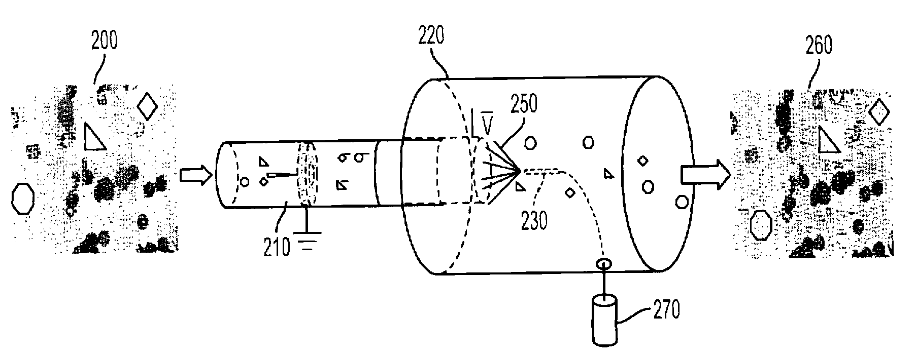
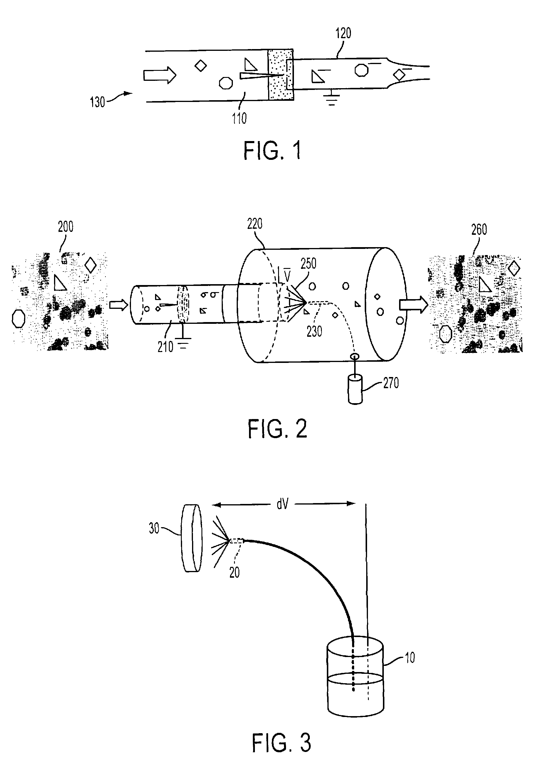
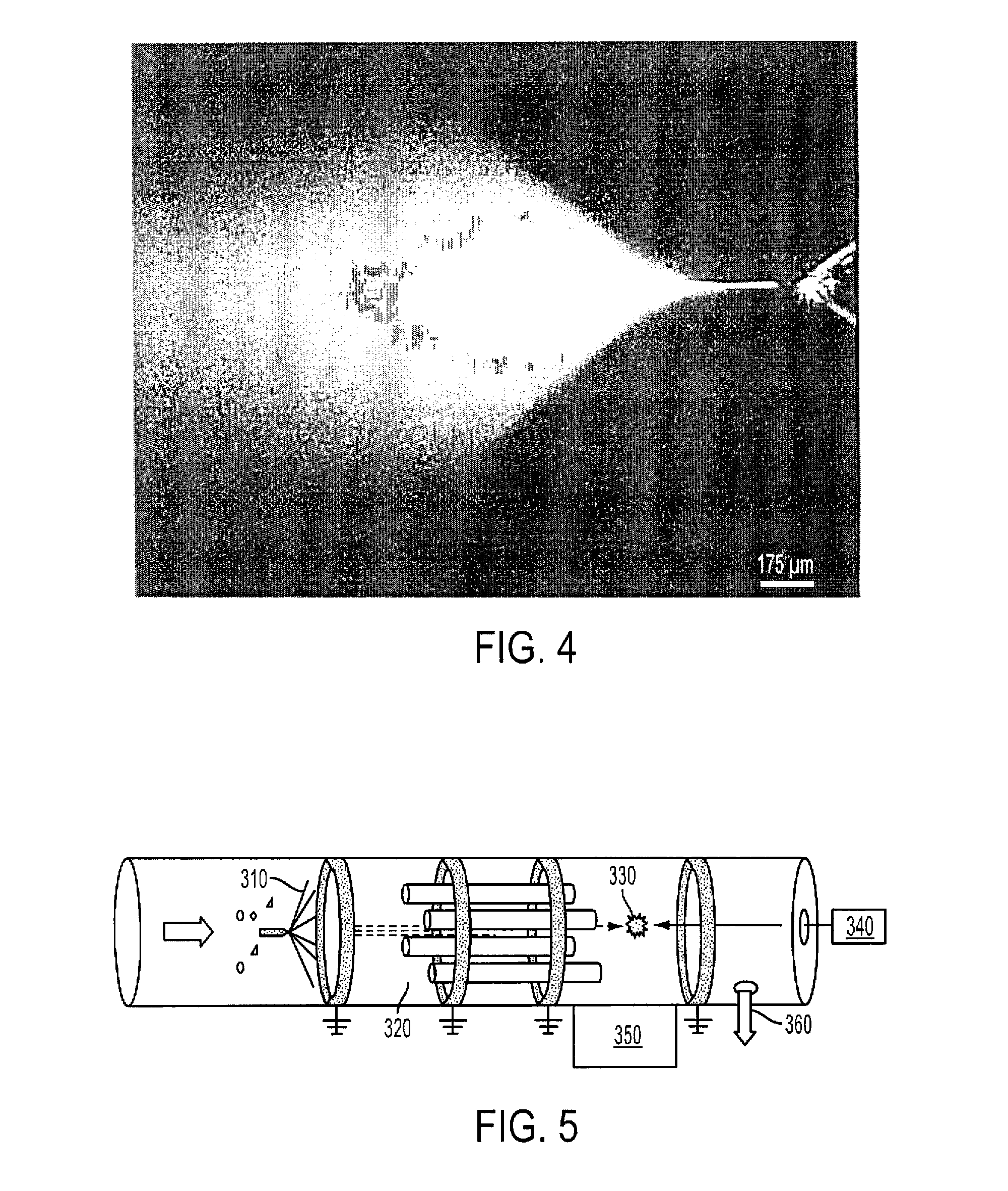
[0032]A prototype was built to demonstrate the basic coating principle based on the electrospray technique. A diagram of the laser interrogation section setup is shown in FIG. 6. The prototype consisted of a 14 inch long, clear plastic tube with an inside diameter of 1.5 inches. The electrospray area (not shown) made up the left section of the tube, and a simple laser interrogation stage (LIS) was in the right half of the tube. Air flow was achieved, from left to right, with the use of a pump connected on the right side of the tube. A green laser beam 410 was directed through a focusing optic 420 along the axis of the tube, from right to left, and illuminated the electrospray area inside the tube and an aperture outside of the tube near the right end, where the light passed into the LIS through a window. Aerosols were sucked into the tube from the left end, passed through the electrospray portion, through an aerodynamic nozzle 480 and then into the LIS. With flow rates of one to 10 ...


PUM

PropertyMeasurementUnit
voltage potentialaaaaaaaaaa
air flow ratesaaaaaaaaaa

Abstract

A device having an air sampler, an electrospray apparatus, and a fluorescence excitation and detection system. The air sampler is capable of moving air suspected of containing a biological or chemical aerosol particle into a chamber. The electrospray apparatus is capable of spraying a charged solution into the chamber to coat the aerosol particles with a coating. The solution has a fluorescent-labeled biological or chemical marker capable of specific binding to the aerosol particle. The fluorescence system is capable of detecting fluorescence of the fluorescent label in the coating. A method of detecting the aerosol particle by: moving air suspected of containing the aerosol particle into a chamber; spraying the charged solution into the chamber with an electrospray apparatus, such that a coating of the solution is formed around the particle; exciting the fluorescent label; and detecting fluorescence of the fluorescent label.

Description

BACKGROUND OF THE INVENTION[0001]1. Field of the Invention[0002]The invention is generally related to biological and chemical detection.[0003]2. Description of the Related Art[0004]Antibody conjugated fluorescent tagging (ACFT) has been used to locate and identify specific biological organisms based on antigen / antibody recognition and binding. If a sample contains the entity for which the antibodies are matched, they will bind to it. Antibodies, or other types of molecular binding entities such as molecular beacons or aptamers can be prepared with fluorescent markers, so when the sample mixture is rinsed the target species can be identified using optical methods. Through the use of self quenching or fluorescence resonant energy transfer (FRET), binding entities can be produced which do not fluoresce unless bound, creating a fluorescent switch to signal the presence of the targeted antigen. The use of these may allow for the labeling and subsequent identification of multiple types of...

Claims


Application Information

Patent Timeline
Patent Type & Authority Patents(United States)
IPC IPC(8): G01N30/96
CPCG01N33/54386G01N15/1459G01N2015/0046
Inventor HART, MATTHEWLIN, HORN BONDEVERSOLE, JAY
Owner THE UNITED STATES OF AMERICA AS REPRESENTED BY THE SECRETARY OF THE NAVY
Why Eureka
Try Eureka