Oxidative autothermal reformer and oxidative autothermal reforming method using the same

a technology of autothermal reformer and autothermal reformer, which is applied in the direction of electrochemical generator, physical/chemical process catalyst, carburetor gas, etc., can solve the problems of non-uniform temperature at each of the layers, difficult to uniformly flow the mixture of hydrocarbons or aliphatic, and difficult to achieve uniform temperature at each layer, etc., to achieve fast heat transfer, easy to use, and easy to achieve the effect of partial heat stress

Inactive Publication Date: 2011-07-19
JAPAN ENERGY CORP +1
View PDF15 Cites 1 Cited by
  • Summary
  • Abstract
  • Description
  • Claims
  • Application Information

AI Technical Summary

Benefits of technology

[0005]It is, therefore, an object of the invention to solve the above-mentioned problems of the conventional techniques and to provide a reformer having a high durability and capable of accomplishing a high reforming efficiency because of a high reaction uniformity in the reforming layer and the oxidative exothermic layer and being particularly suitable for reforming a hydrocarbon-based starting material having a larger carbon number, which was deemed difficult to be reformed, as well as a reforming method using the reformer.
[0014]In the oxidative autothermal reformer according to the invention, it is preferable that a tubular ring provided with a plurality of ports for blowing out an oxidizing gas is disposed in the oxidative exothermic layer as a means for feeding the oxidizing gas to the oxidative exothermic layer. In this case, the oxidizing gas is uniformly diffused into the oxidative exothermic layer, whereby the oxidation reaction in the cross-sectional direction of the oxidative exothermic layer can be easily caused evenly.
[0019]In a preferable embodiment of the oxidative autothermal reforming method according to the invention, a mixture containing an oxidation catalyst and a reforming catalyst is filled into the oxidative exothermic layer, the mixture of the hydrocarbon or aliphatic alcohol and steam is fed to the inner reforming layer and the outer reforming layer to produce the reformed gas composed mainly of hydrogen through the reforming reaction, and then the reformed gas is fed to the oxidative exothermic layer to oxidize a part of the reformed gas to generate heat with further promoting the reforming of the reformed gas. When the reforming reaction is conducted only in the inner reforming layer and the outer reforming layer, an amount of methane and / or a component having a carbon number of not less than 2 (C2+ component) retaining in the reformed gas may be large. In the latter method, however, the reforming reaction can be promoted even in the oxidative exothermic layer, and hence the amount of methane and / or the C2+ component retaining in the reformed gas can be further reduced to increase a total amount of the resulting hydrogen.
[0023]Also, the heat transfer area can be enlarged to more quickly transfer the heat generated in the oxidative exothermic layer to the reforming layer by dividing the reforming layer into two layers (the inner reforming layer and the outer reforming layer) and sandwiching the oxidative exothermic layer therebetween, and thereby the temperature distribution in a cross-sectional direction of the reforming layer can be made more uniform.
[0024]Further, since the reformer has the triple circular tube structure, the partial heat stress can be hardly caused to improve the durability of the reformer.
[0025]Moreover, the reforming efficiency of the liquid fuel can be improved by filling the inner reforming layer and the outer reforming layer with the reforming catalyst containing Ru metal. Although the reforming catalyst containing Ru metal is commonly low in the oxidation resistance, the oxidizing gas is not fed into the inner reforming layer and the outer reforming layer in the invention, so that it is not necessary to take account of the oxidation resistance of the catalyst and the Ru-supported catalyst can be preferably used.

Problems solved by technology

In the methods described in the above official gazettes, however, the reforming layer and the oxidative exothermic layer are in the form of a rectangular column, so that it is difficult to uniformly flow the mixture of the hydrocarbon or aliphatic alcohol and steam and / or the reformed gas therefrom through the reforming layer and the oxidative exothermic layer and also the temperature at each of the layers tends to be non-uniform.
Therefore, there is a problem that the reforming reaction does not evenly progress at the reforming layer, and in particular there are caused many problems when a hydrocarbon having a large carbon number is used as a starting material.
Since the reformer is in the form of the rectangular column, the temperature at each catalyst layer also becomes non-uniform, and hence high-temperature and low-temperature portions are partially formed in the wall of the reformer, which also causes a problem in the durability of the reformer due to heat stress therefrom.
Also, it has been found that since the reformer has the triple circular tube structure, partial heat stress is hardly caused to improve the durability of the reformer.

Method used


Image

  • Oxidative autothermal reformer and oxidative autothermal reforming method using the same
  • Oxidative autothermal reformer and oxidative autothermal reforming method using the same
  • Oxidative autothermal reformer and oxidative autothermal reforming method using the same

Examples


Embodiment Construction

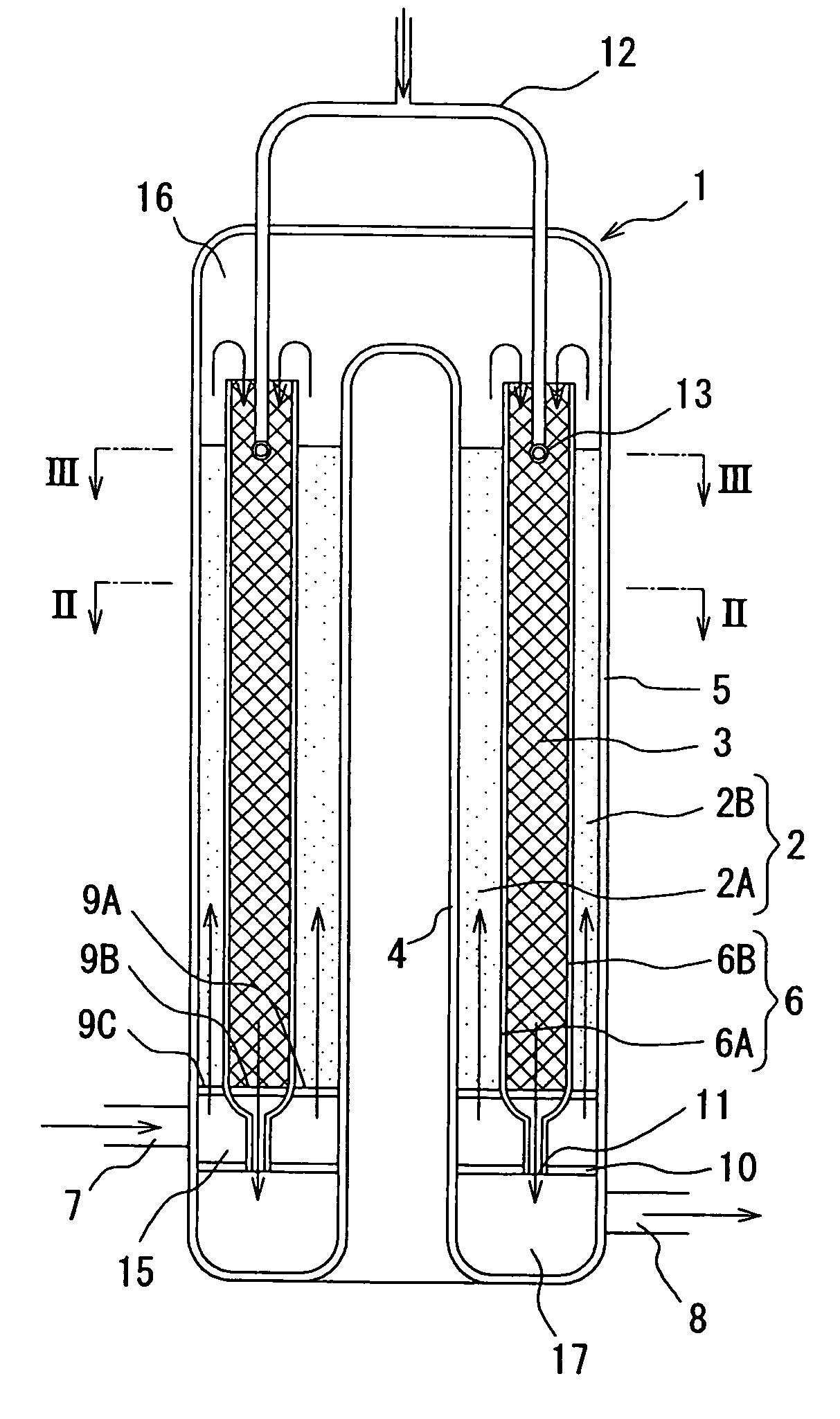
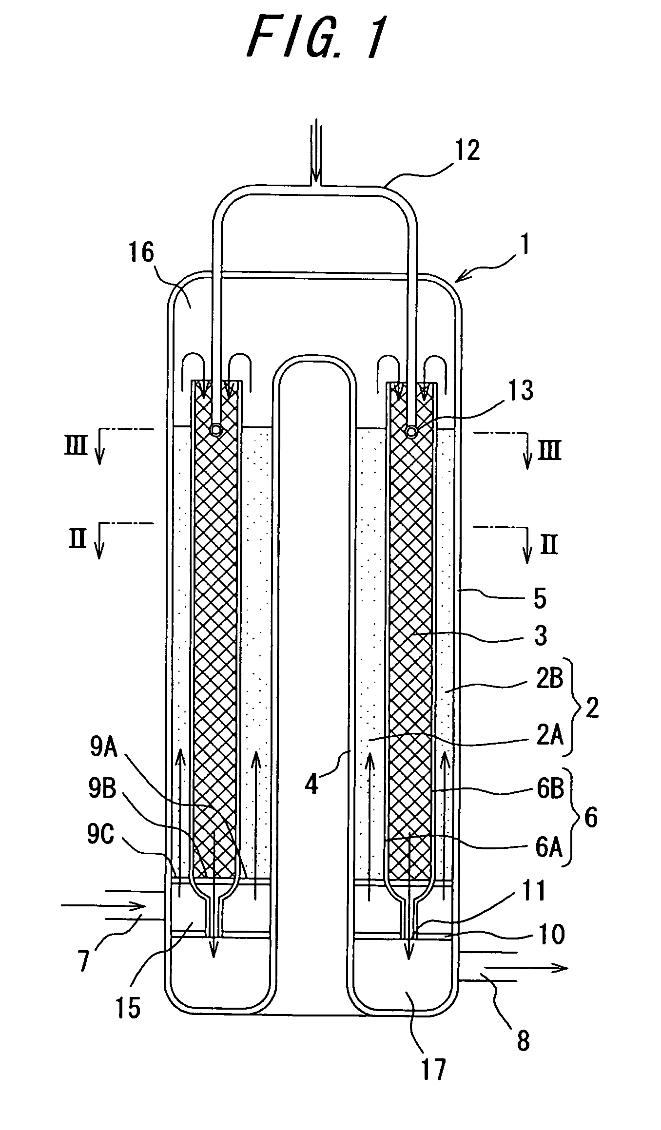
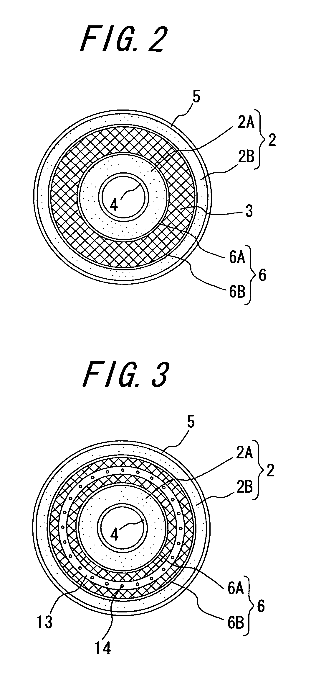
[0030]An embodiment of the invention will be described in detail below with reference to the attached drawings. FIG. 1 is a schematic view of an embodiment of the oxidative autothermal reformer according to the invention, and FIG. 2 is a cross-sectional view taken along a line II-II in FIG. 1, and FIG. 3 is a cross-sectional view taken along a line III-III in FIG. 1, and FIG. 4 is a schematic view of another embodiment of the oxidative autothermal reformer according to the invention. The oxidative autothermal reformer has a cylindrical form as a whole, and each of elements is formed circularly and disposed concentrically.

[0031]The illustrated oxidative autothermal reformer 1 comprises a reforming layer 2 and an oxidative exothermic layer 3 wherein the reforming layer 2 is positioned at an upstream side of the oxidative exothermic layer 3. The reforming layer 2 and the oxidative exothermic layer 3 have the cylindrical form, respectively, and the reforming layer 2 is comprised of two ...


PUM

PropertyMeasurementUnit
temperatureaaaaaaaaaa
volume ratioaaaaaaaaaa

Abstract

An oxidative autothermal reformer including a reforming layer at least partially filled with a reforming catalyst for producing a reformed gas composed mainly of hydrogen through a reforming reaction by contacting a mixture of a hydrocarbon or an aliphatic alcohol and steam with the reforming catalyst; and an oxidative exothermic layer at least partially filled with an oxidation catalyst for generating heat by oxidizing a part of the reformed gas, in which the reforming layer is disposed at an upstream side of the oxidative exothermic layer; the reforming layer and the oxidative exothermic layer are in the form of a cylinder and have a triple circular tube structure formed by disposing an inner reforming layer, an oxidative exothermic layer and an outer reforming layer from the inside in a radial direction in this order; and at least a part of the reforming catalyst filled in the inner reforming layer and the outer reforming layer contains Ru metal.

Description

TECHNICAL FIELD[0001]This invention relates to a reformer for contacting a mixture of a hydrocarbon or an aliphatic alcohol and steam with a reforming catalyst to produce a reformed gas composed mainly of hydrogen through a reforming reaction and a reforming method using the reformer, and more particularly to an oxidative autothermal reformer utilizing heat of oxidation in the reformer for the reforming reaction.BACKGROUND ART[0002]Heretofore, as a method for producing a reformed gas composed mainly of hydrogen through a reforming reaction by contacting a mixture of a hydrocarbon or an aliphatic alcohol and steam with a catalyst is adopted a steam reforming system wherein heat required for the reforming reaction (endothermic reaction) is given from an exterior through a wall of the reformer as a heat transfer face by means of a combustion burner or the like. In this system, however, for example, when kerosene is steam-reformed, a reforming reaction temperature is required to be abou...

Claims


Application Information

Patent Timeline
Patent Type & Authority Patents(United States)
IPC IPC(8): B01J8/04
CPCB01J8/0446B01J8/0496C01B3/38C01B3/382B01J2208/00309C01B2203/0233C01B2203/0244C01B2203/0261C01B2203/066C01B2203/1058C01B2203/1064C01B2203/1217C01B2203/1235C01B2203/1252C01B3/32
Inventor YAMAZAKI, YOSHINORIMARUKO, SABUROKOMORI, SHINGO
Owner JAPAN ENERGY CORP
Why Eureka
Try Eureka