Optical disk apparatus

a technology of optical disk and optical disk, which is applied in the field of optical disk apparatus, can solve the problems of reducing the resolution of the reproduction sum signal, affecting so as to improve the quality of the reproduction signal, and reduce the resolution of the reproduction signal.

Inactive Publication Date: 2011-07-19
TEAC CORP
View PDF8 Cites 1 Cited by
  • Summary
  • Abstract
  • Description
  • Claims
  • Application Information

AI Technical Summary

Benefits of technology

[0011]The present invention provides an optical disk apparatus capable of reliably compensating for a phase difference between signals on a leading side and signals on a following side, which change in various manners according to the type of an optical disk, and reducing a decrease in resolution of a reproduction sum signal, to there by improve the quality of a reproduction signal by means of reducing the resolution of a reproduction sum signal.
[0014]According to the present invention, a phase difference between the two clock signals used for instructing conversion timing of the analog-to-digital conversion means (A / D) is adjusted, thereby compensating for a phase difference between the first reproduction RF signal and the second reproduction RF signal. In the present invention, conversion timing; i.e., sampling timing, is adjusted to thus compensate for a phase difference. Accordingly, even when the phase difference between the first reproduction RF signal and the second reproduction RF signal has changed in various manners according to the type of the optical disk and the reproduction speed, a decrease in the resolution of a reproduction sum signal is avoided by means of correspondingly adjusting the phase difference between the clock signals in an adaptive manner, thereby ensuring the quality of the reproduction signal.
[0015]Further, according to the present invention, RF signals from the respective elements acquired by splitting are delayed, as appropriate, and the thus-delayed signals are summed. Thus, the PR class is substantially converted, and hence the amplitude of a short signal, such as a 2T signal, can be readily detected.

Problems solved by technology

When such a phase lag has arisen, a decrease occurs in the resolution of the reproduction RF signal that is the sum of these signals, and an increase in jitter or deterioration of quality of a reproduction signal is induced during demodulation.
Hence, the phase difference cannot be compensated for by means of advancing or delaying a phase in an analog fashion by the advancement means, so that the quality of a reproduction signal cannot be sufficiently improved.

Method used


Image

  • Optical disk apparatus
  • Optical disk apparatus
  • Optical disk apparatus

Examples


first embodiment

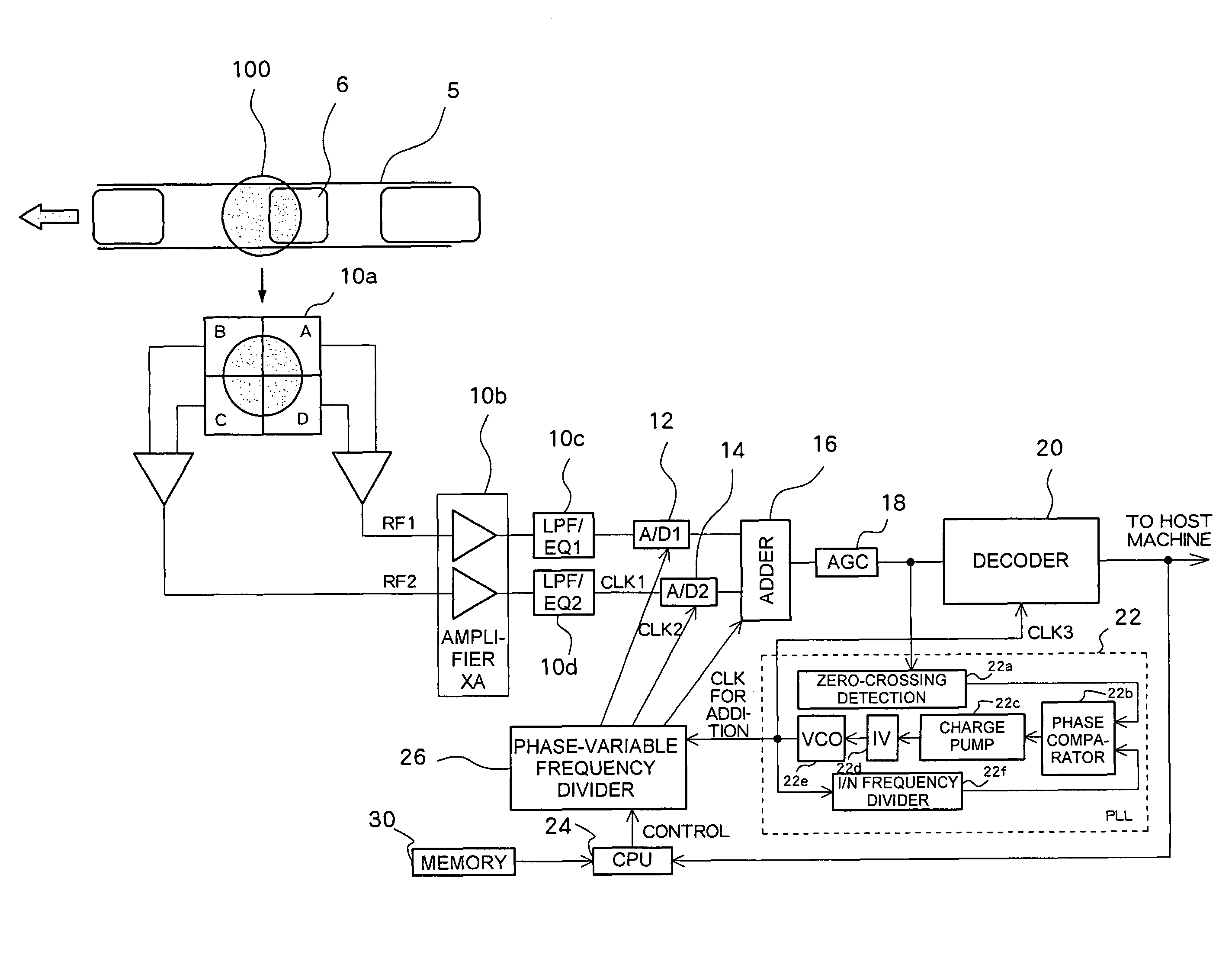
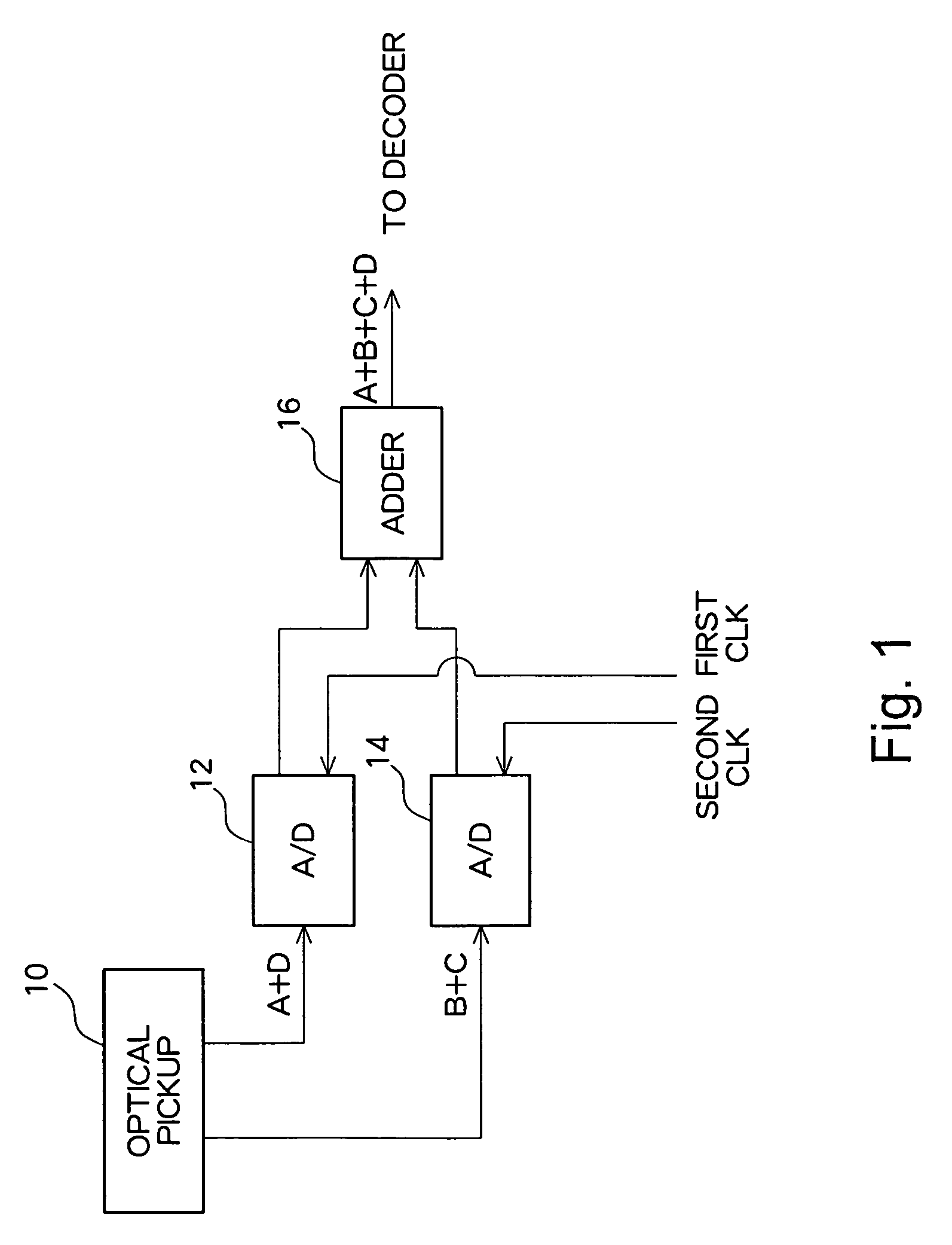
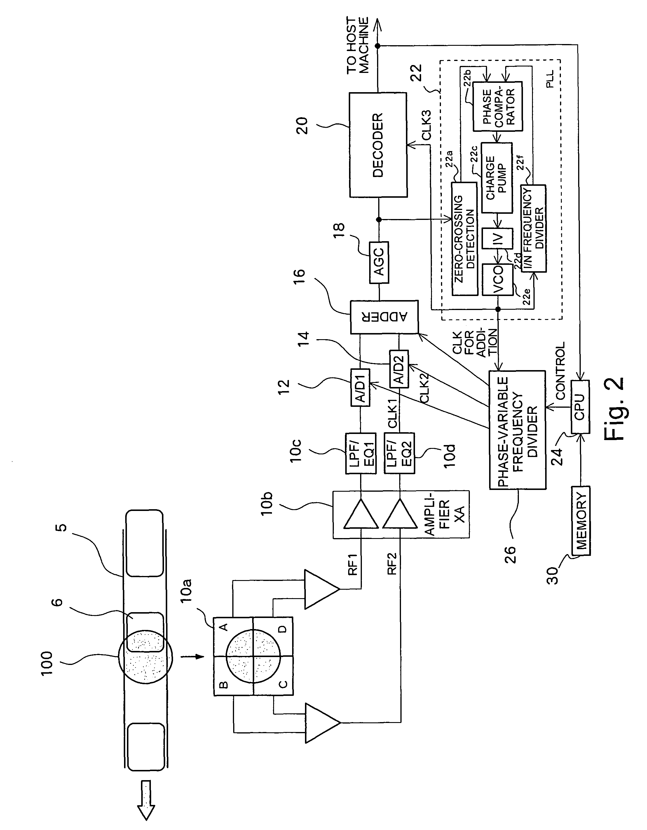
[0029]FIG. 1 shows a conceptual configuration of an optical disk apparatus according to a first embodiment of the present invention. The optical disk apparatus broadly has a recording system for recording data and a reproduction system for reproducing the data recorded in an optical disk. However, since the configuration of the recording system is analogous to a well-known configuration, only the configuration of the reproduction system is shown.

[0030]In addition to including a light source and a lens which are used for radiating a laser beam on an optical disk, an optical pickup 10 includes a four-quadrant photodetection section which subjects light reflected from the optical disk to photoelectric conversion to thereby output an RF signal. During reproduction of data, a laser beam of reproduction power is emitted from the light source, and respective detectors of the four-quadrant photodetection section receive the reflected light and output the light in the form of RF signals. As ...


PUM

PropertyMeasurementUnit
phaseaaaaaaaaaa
optimal phase differenceaaaaaaaaaa
optimal phaseaaaaaaaaaa

Abstract

An optical disk apparatus for enhancing time resolution of an RF sum signal. A reproduction sum signal (a signal A+a signal D) on the leading side and a reproduction sum signal (a signal B+a signal C) on the following side, which have been output from a four-quadrant photodetection section of an optical pickup, are supplied to first and second A / D converters. The first A / D converter samples a signal in accordance with a first clock signal CLK, and the second A / D converter samples a signal in accordance with a second clock signal CLK. The first and second clock signals CLK are out of phase with each other. By means of a phase difference between the clock signals, a phase difference between the leading-side reproduction signals and the following-side reproduction signals is compensated for. The phase difference between the first and second clock signals CLK is adjusted such that the quality of a reproduction signal, such as jitter, an error rate, or the like, is optimized.

Description

PRIORITY INFORMATION[0001]This application claims priority to Japanese Patent Application No. 2005-310322 filed on Oct. 25, 2005 and Japanese Patent Application No. 2006-237605 filed on Sep. 1, 2006, which are incorporated herein by reference in their entireties.BACKGROUND OF THE INVENTION[0002]1. Technical Field[0003]The present invention relates to an optical disk apparatus and, more particularly, to processing of a reproduction signal output from a split photodetection section.[0004]2. Related Art[0005]A known optical disk apparatus hitherto radiates, on an optical disk, a laser beam of reproduction power from a laser diode of an optical pickup; subjects light reflected from the optical disk to photoelectric conversion performed by a four-quadrant photodetection section of the optical pickup; and adds signals output from respective photodetectors of the four-quadrant photodetection section, thereby acquiring a reproduction RF signal. When the laser beam of reproduction power pass...

Claims


Application Information

Patent Timeline
Patent Type & Authority Patents(United States)
IPC IPC(8): G11B20/00
CPCG11B20/10009
Inventor UENO, KEISHI
Owner TEAC CORP
Why Eureka
Try Eureka