Steam turbines, seals, and control methods therefor

a steam turbine and seal technology, applied in the direction of machines/engines, stators, liquid fuel engines, etc., can solve the problems of difficulty in practical application and lack of appropriate measures, and achieve the effect of improving the efficiency of the steam turbine, shortening the time required for unsteady operation, and reducing the leakage of steam during operation

Inactive Publication Date: 2011-07-26
MITSUBISHI POWER LTD
View PDF4 Cites 9 Cited by
  • Summary
  • Abstract
  • Description
  • Claims
  • Application Information

AI Technical Summary

Benefits of technology

It is an object of the present invention to improve the efficiency of a steam turbine.
According to the present invention it is possible to suppress the leakage of steam during operation of the steam turbine while shortening the time required for unsteady operation and hence possible to improve the efficiency of the steam turbine.

Problems solved by technology

However, the above technique premises warming-up or cooling of the entire casing and is less effective in the case where steam necessary for warming up or cooling the casing cannot be supplied sufficiently, thus its practical application sometimes encounters difficulty.
Besides, as to improving the efficiency in steady operation which is associated with shortening the unsteady operation time by preheating or precooling, no appropriate measure has been considered.

Method used


Image

  • Steam turbines, seals, and control methods therefor
  • Steam turbines, seals, and control methods therefor
  • Steam turbines, seals, and control methods therefor

Examples


first embodiment

First, a description will be given about the present invention with reference to FIGS. 1 to 7.

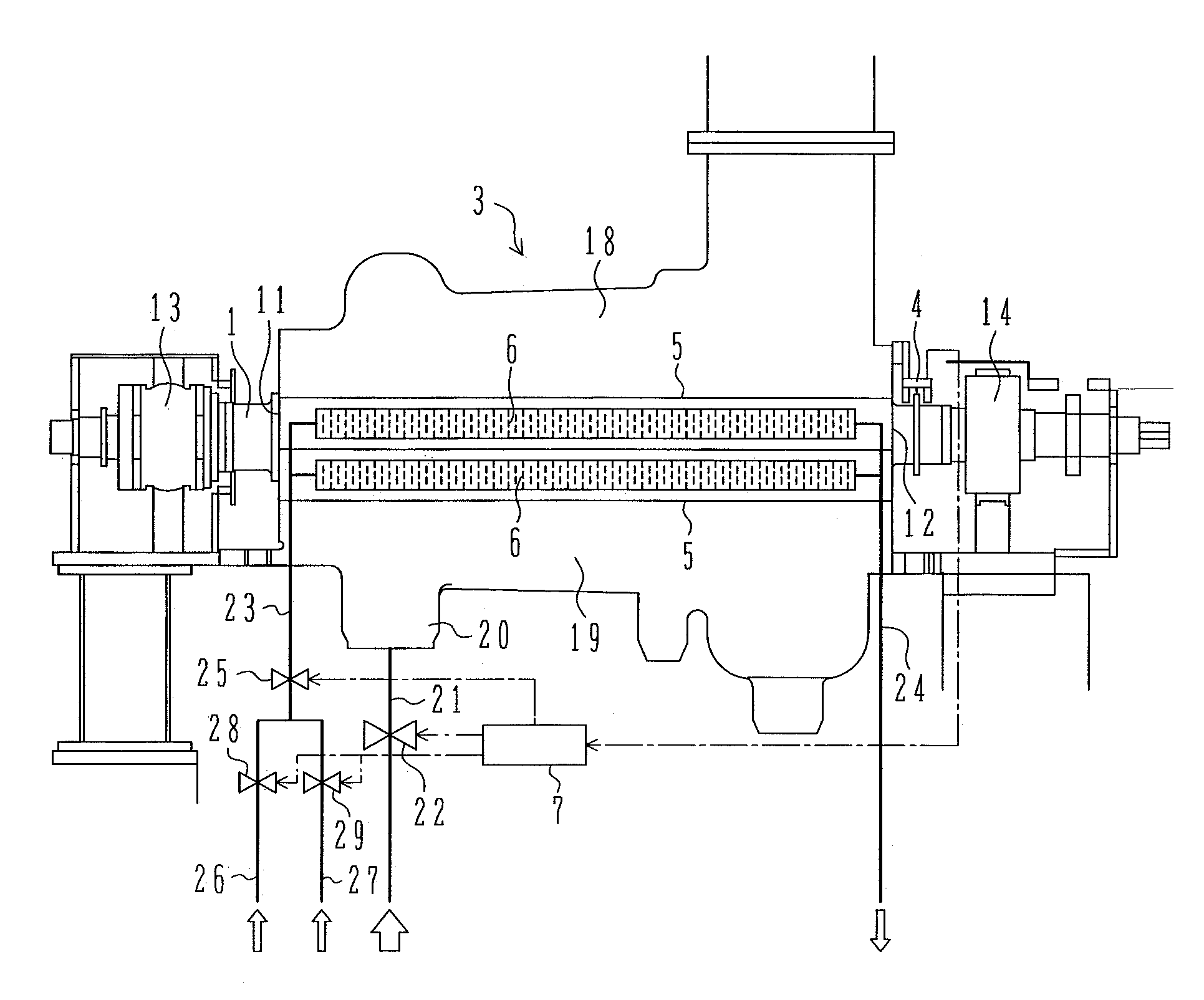
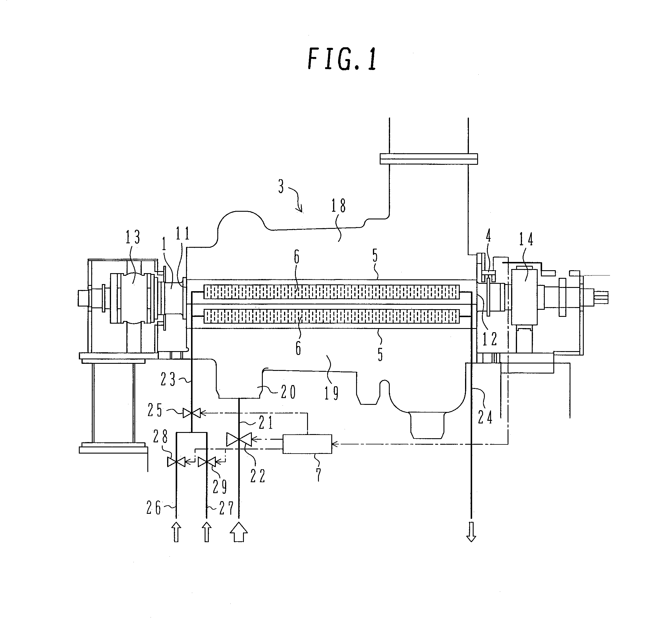
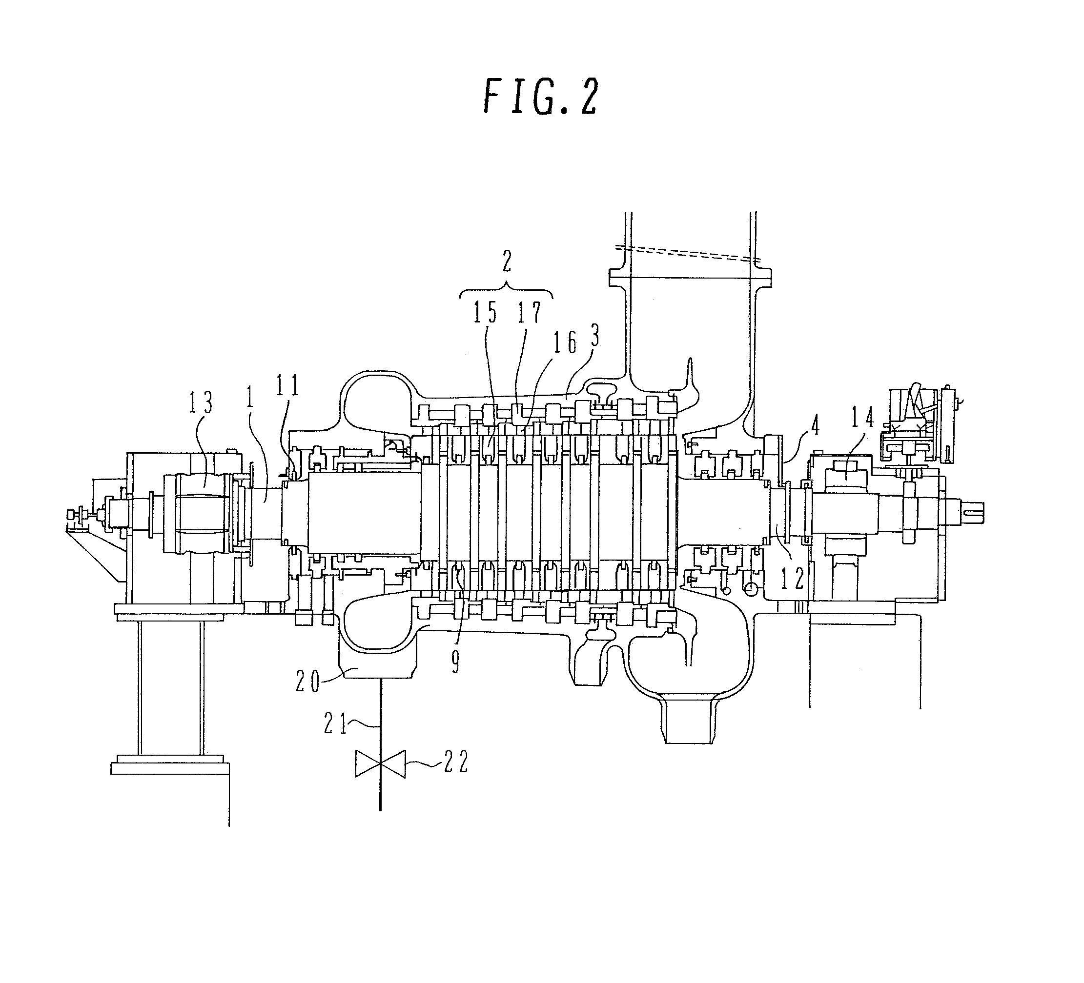
FIG. 1 is a side view of a steam turbine according to a first embodiment of the present invention, FIG. 2 is a sectional view thereof, FIG. 3 is an enlarged diagram of a rotor and the vicinity thereof in the steam turbine shown in FIG. 1, and FIG. 4 is an enlarged, schematic side view of a seal body in the steam turbine shown in FIG. 1.

The illustrated steam turbine of the first embodiment mainly includes a rotor 1, diaphragms 2 which surround the rotor annularly from the outer periphery side of the rotor, a casing 3 which encloses the diaphragms 2 and the rotor 1, a displacement detector 4 for measuring a difference (designated “d”) in thermal expansion between the casing 3 and the rotor 1, heating / cooling devices 6 attached to flanges 5 of the casing 3 to heat or cool the flanges, a controller 7 which makes control so that the flanges 5 are heated or cooled by the heating / cooling devices 6...

second embodiment

the present invention will be described below.

A main feature of this second embodiment resides in that heating or cooling of the flanges 5 of the casing 3 is started after moving the seal bodies radially outwards of the rotor 1 and the seal bodies are moved back to their original positions after stop of the cooling or heating, thereby eliminating the problem caused by a thermal expansion difference.

FIG. 9 is a side view of a steam turbine according to a second embodiment of the present invention and FIG. 10 is a sectional view thereof. FIGS. 11A and 11B are enlarged views of a portion XI indicated with a dotted line in FIG. 10, of which FIG. 11A shows a state in which seal bodies have been moved radially outwards of the rotor and FIG. 11B shows a state in which the seal bodies are in neutral positions. The same portions as in the previous drawings are identified by the same reference numerals as in the previous drawings and explanations thereof will be omitted.

The illustrated steam ...

third embodiment

the present invention will be described below.

This third embodiment is the same as the first embodiment in that the expansion difference d is controlled by the controller 7B without retracting seal bodies radially outwards of the rotor 1. In this connection, this third embodiment is characteristic in that when sealing fins are likely to contact one another, the steam turbine is controlled so as to minimize the time required for retracting the seal bodies radially outwards of the rotor 1. A mechanical structure of the steam turbine of this embodiment is the same as that of the second embodiment and therefore explanations of its constituent elements will be omitted.

The controller 7B used in this embodiment, as in the second embodiment, also uses the expansion difference d as an index to determine the timing for opening or closing each of the valves 22, 25, 28, 29 and 47 and, as preset values to be stored in advance, it stores a preset value Z which is the fourth type of a preset value...


PUM


Abstract

A steam turbine comprises a rotor with moving blades attached thereto; diaphragms which surround the rotor from an outer periphery side of the rotor; a casing which encloses the diaphragms and the rotor and has an upper half and a lower half clamped together through respective flanges; a displacement detector for measuring a difference d in thermal expansion in the rotor axis direction between the casing and the rotor; heating / cooling devices attached to the flanges respectively to heat and cool the flanges; and a controller which makes control so that the flanges are heated or cooled by the heating / cooling devices until a measured value obtained by the displacement detector reaches a preset value M or S in unsteady operation.

Description

BACKGROUND OF THE INVENTION1. Field of the InventionThe present invention relates to steam turbines for obtaining energy with use of steam, seals disposed outside the steam turbines in a rotor radial direction to suppress the leakage of steam, and methods for controlling the steam turbines and the seals.2. Description of the Prior ArtAs one effective means for improving the efficiency of a steam turbine it is known to shorten the time required for unsteady operation such as start and stop of the steam turbine.Usually, when starting up a steam turbine, a relative rotor expansion in the corresponding cylinder caused by a difference in heat capacity between a rotor with moving blades attached thereto and a casing which houses the rotor therein is controlled by warming up the steam turbine gradually. In this way the state of the steam turbine is changed slowly up to the state of its steady operation while preventing the rotor relatively small in heat capacity in comparison with the casi...

Claims


Application Information

Patent Timeline
Patent Type & Authority Patents(United States)
IPC IPC(8): F01D21/14
CPCF01D11/02F01D11/025F01D25/14F05D2220/31F05D2260/80F05D2260/2322F05D2260/20F05D2260/232
Inventor NARITA, KENJIROKUDO, TAKESHI
Owner MITSUBISHI POWER LTD
Why Eureka
Try Eureka