Solar heat collection device and sewage treatment method thereof

A technology of solar heat collection and heat collection devices, which is applied in the field of solar energy, can solve the problems that metal ions cannot be precipitated, can not be satisfied, can not solve the problem of sediment discharge such as sewage sedimentation, sludge impurities, etc., and achieve heat loss suppression, The effect of reducing cost, broad commercial value and application prospect

Active Publication Date: 2021-06-25
SHANDONG UNIV
View PDF6 Cites 2 Cited by
  • Summary
  • Abstract
  • Description
  • Claims
  • Application Information

AI Technical Summary

Problems solved by technology

[0007] In the modernization of the city, industrial development plays an extremely important role. However, with the rapid development of industry, the environmental problems caused by industrial sewage have also attracted people's attention. These sewage contain more heavy metal ions. Before the treatment, simple desalination treatment should be carried out, and the sewage with high heavy metal ion content should be subjected to simple ion precipitation treatment, which is convenient for systematic treatment in the later stage. Some devices on the market have some defects and cannot solve the sewage sedimentation well. The discharge of sediments such as residual sludge impurities in the sewage can not efficiently separate the metal ions in the sewage, and cannot meet the requirements of modern sewage treatment

Method used


Image

  • Solar heat collection device and sewage treatment method thereof
  • Solar heat collection device and sewage treatment method thereof
  • Solar heat collection device and sewage treatment method thereof

Examples


Embodiment Construction

[0039] The specific embodiments of the present invention will be described in detail below with reference to the accompanying drawings.

[0040] In this article, if there are no special instructions, when it comes to formulas, " / " means division, and "×" and "*" mean multiplication.

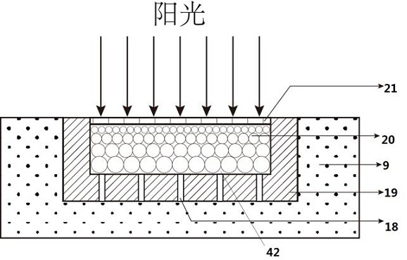
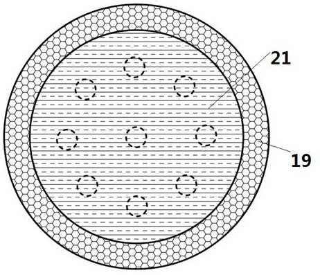
[0041] like Figure 1-3 As shown, a device for extracting water from solar heat collection sewage, the device includes a water tank 9 and a light-to-heat conversion element, the upper end of the water tank is an open structure, the light-to-heat conversion element floats on the upper part of the water tank 9, and the light The heat conversion element comprises a base body 19 formed of a foamed material, a groove 42 with an upper side opening is formed on the base body 19, the groove 42 is filled with a foamed nickel base 20, and the lower wall of the base body 19 is provided with a capillary structure water conveyance channel 18, so The water channel 18 communicates with the water body of the wa...


PUM

PropertyMeasurementUnit
diameteraaaaaaaaaa
heightaaaaaaaaaa
radiusaaaaaaaaaa

Abstract

The invention provides a solar heat collection device and a sewage treatment method thereof. The solar heat collection device comprises a reflecting mirror, the reflecting mirror is divided into two parts along the middle, the two parts are the first part and the second part separately, a supporting piece is arranged on the lower portion of a heat collection pipe box, and two hydraulic telescopic rods stretch out of a supporting column to be connected to the first part and the second part separately. The two hydraulic telescopic rods are used for driving the first part and the second part to separate or combine. When the first part and the second part are combined together, the reflecting mirror bodies form the complete reflecting mirror, and the heat collection pipe box is located at the focus position of the reflecting mirror and used for collecting heat of the heat collection pipe box; and when the first part and the second part are separated, the heat collection pipe box is not located at the focus of the first part and the second part, and heat collection is not conducted on the heat collection pipe box. The heat collection device of a novel structure is provided, and vibration and descaling of the heat collection device can be achieved by judging whether heat collection is conducted on the heat collection device or not.

Description

technical field [0001] The invention belongs to the field of solar energy, in particular to a solar heat collector system. Background technique [0002] With the rapid development of modern society and economy, the human demand for energy is increasing. However, the reserves of traditional energy such as coal, oil, and natural gas continue to decrease and become increasingly scarce, resulting in rising prices. At the same time, the environmental pollution caused by conventional fossil fuels is also becoming more and more serious. These greatly limit the development of society and the improvement of human life quality. . Energy issues have become one of the most prominent issues in the contemporary world. Therefore, seeking new energy sources, especially non-polluting clean energy sources has become a research hotspot. [0003] Solar energy is an inexhaustible clean energy with a huge amount of resources. The total amount of solar radiation energy received by the earth's s...

Claims


Application Information

Patent Timeline
Patent Type & Authority Applications(China)
IPC IPC(8): F24S10/30F24S10/70F24S20/20F24S23/70F24S60/10F22B1/00C02F1/14
CPCF24S10/746F24S60/10F24S10/30F24S20/20F24S23/70F22B1/006C02F1/14F24S2020/23Y02A20/212Y02E10/44
Inventor 季万祥袁宝强王湛辛公明刘现综杨绪钦张卫国邓佳王凯贾蓉蓉陈岩郭春生
Owner SHANDONG UNIV
Why Eureka
Try Eureka