Delivery catheter and method of manufacture

Active Publication Date: 2011-07-26
COOK MEDICAL TECH LLC
View PDF14 Cites 38 Cited by
  • Summary
  • Abstract
  • Description
  • Claims
  • Application Information

AI Technical Summary

Benefits of technology

[0010]The foregoing problems are solved and a technical advance is achieved in an illustrative delivery catheter/sheath, which has an enlarged lumen or passageway at the distal end portion of the catheter than that of the remaining proximal portion of the delivery catheter/sheath. As a result, the outer diameter of the delivery catheter is advantageously reduced to reduce bleeding at the access site and to navigate smaller diameter and tortuous vessels. By way of example, the same self-expanding ZILVER stent as used in the commercially available 7 French delivery system can now be positioned in and delivered with a reduced diameter 6 French delivery system. This illustrative delivery catheter/sheath comprises a first or inner tube having a lumen or passageway extending longitudinally therein. A second or outer tube is positioned around and proximal a distal portion of the first or inner tube. The distal portion of the first or inner tube includes first and second coaxial layers, which are formed when the inner tube is

Problems solved by technology

These sheaths are of a thin-wall construction, but tend to kink.
Increasing the thickness of the sheath wall minimally improves the level of kink resistance, which is still unacceptable.
Sheaths used in hemofiltration and dialysis, in particular, are prone to kinking since they remain positioned in a patient's body for a long time.
While positioned in a patient, the sheath may be bent or pinched off and, as a result, kink due to repeated use or patient movement.
A kinked sheath is unusable and cannot be straightened while positioned in the body of a patient.
Consequently, the sheath must be removed, leaving an enlarged, bleeding opening, which typically cannot be reused.
Restarting the procedure causes a time delay, which may be life threatening.
In some cases, an alternative site is not available for introducing another sheath.
Another problem with thin-wall sheaths is that an emergency room physician will typically kink an introducer sheath while inserting

Method used


Image

  • Delivery catheter and method of manufacture
  • Delivery catheter and method of manufacture
  • Delivery catheter and method of manufacture

Examples


Embodiment Construction

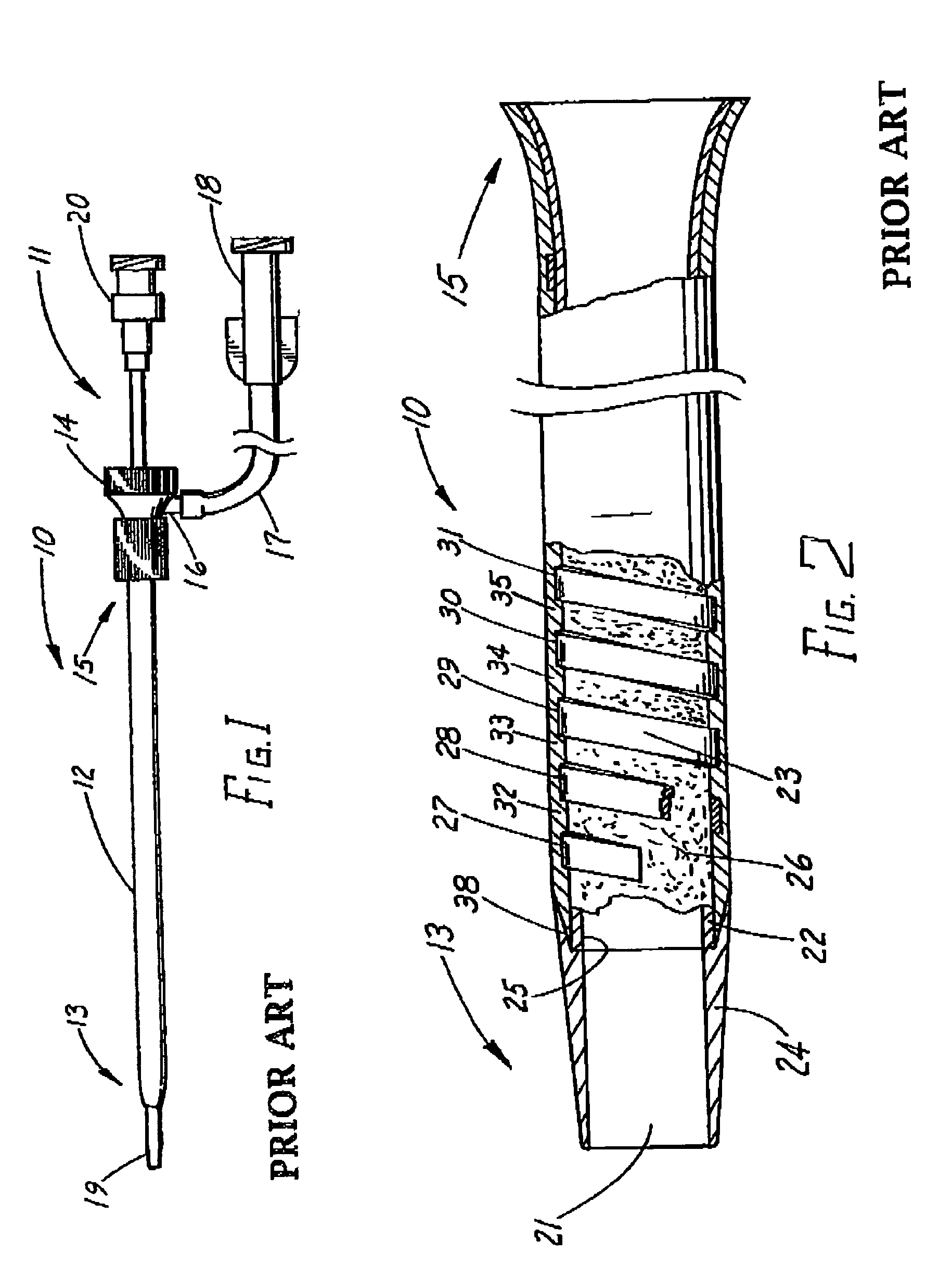
[0040]FIG. 1 depicts an illustrative flexible, kink-resistant, introducer sheath 10 with a tapered dilator 11 extending longitudinally through the passageway of the sheath. As shown, the introducer sheath includes an outer tube 12 with a tapered distal end 13 and connector valve 14 attached about proximal end 15 of the sheath. Well-known connector valve 14 includes a silicone disk (not shown) for preventing the backflow of fluids therethrough. The disk includes a slit for the insertion of dilator 11. Byway of example, the dilator 11 has a 6.0 French (0.079″) outside diameter. Connector 14 also includes side arm 16 to which polyvinyl tube 17 and male Luer lock connector 18 are connected for introducing and aspirating fluids therethrough. Dilator 11 includes tapered distal end 19 for accessing and dilating a vascular access site over a well-known and commercially available wire guide. The guide is inserted in the vessel with an introducer needle using, for example, the well-known perc...


PUM

PropertyMeasurementUnit
Diameteraaaaaaaaaa
Flexibilityaaaaaaaaaa
Melting pointaaaaaaaaaa

Abstract

A flexible, kink-resistant, delivery catheter or sheath (83) for percutaneously delivering implantable medical devices. The delivery catheter sheath includes a flat wire coil (95) with uniform spacing between the turns, which is compression fitted about and proximal the distal portion of an inner, lubricous material polytetrafluoroethylene tube (84). The delivery catheter or sheath further includes an outer tube (85) of a heat formable polyamide material, which is heat formed and compressed through the spaces between the turns of the wire coil to mechanically connect to the roughened outer surface of the inner tube. The distal portion (87) of the inner tube is expanded and everted or folded-back over itself and connected to the distal end of the outer tube to form a lumen having a larger diameter than the rest of the catheter.

Description

CROSS-REFERENCE TO RELATED APPLICATIONS[0001]This application claims priority of provisional application Ser. No. 60 / 465,368, filed Apr. 25, 2003.TECHNICAL FIELD[0002]This invention relates generally to medical devices and, in particular, to delivery catheters / sheaths for delivering implantable medical devices to, for example, a vascular deployment site.BACKGROUND OF THE INVENTION[0003]Introducer sheaths are well-known for percutaneous vascular access and typically comprise polytetrafluoroethylene or fluorinated ethylene propylene. These sheaths are of a thin-wall construction, but tend to kink.[0004]Increasing the thickness of the sheath wall minimally improves the level of kink resistance, which is still unacceptable. Sheaths used in hemofiltration and dialysis, in particular, are prone to kinking since they remain positioned in a patient's body for a long time. While positioned in a patient, the sheath may be bent or pinched off and, as a result, kink due to repeated use or patie...

Claims


Application Information

Patent Timeline
IPC IPC(8): A61M25/00A61F11/00A61M25/01
CPCA61M25/0045A61M25/005A61M25/0052
Inventor PARKER, FRED T.
Owner COOK MEDICAL TECH LLC
Why Eureka
Try Eureka