Device for shaping laser radiation

a laser radiation and radiation technology, applied in the direction of instruments, nuclear engineering, optical elements, etc., can solve the problem of design-related brightness limits of the overall laser system, and achieve the effect of greater brightness and better focus

Inactive Publication Date: 2011-07-26
LIMO GMBH
View PDF17 Cites 15 Cited by
  • Summary
  • Abstract
  • Description
  • Claims
  • Application Information

AI Technical Summary

Benefits of technology

[0008]It is an object of the present invention to provide a device of the type mentioned in the introduction, with which the laser radiation output by a laser diode bar can be shaped so that it has a greater brightness and / or it can be focused better.
[0010]According to claim 1, the device comprises a first refractive interface which can differently deviate at least a multiplicity of the sub-beams of the laser radiation to be shaped, so that they travel at least partially converging together after passing through the first interface more than before passing through the first interface, and the device furthermore comprises a second refractive interface through which the laser radiation can pass after having passed through the first interface, the second interface being able to deviate at least some of the sub-beams so that their convergence is reduced. By reducing or eliminating the distance between the sub-beams in the first direction, the dark region between the individual sub-beams can be reduced so that the achievable brightness can be brought closer to the physical limit.
[0013]In particular, the second interface may deviate at least some of the sub-beams so that the convergence of the sub-beams is reduced, such that they travel mutually parallel with deviations of ±10%, preferably ±5%, in particular ±1%. The individual sub-beams can therefore be parallel again after passing through the second refractive interface, the periodicity and dark region being manipulated. A brightness is thereby achieved which is higher than that which is possible with previously available optics.
[0022]As mentioned, previous solutions for the splitting use separate optics. The device according to the invention obviates such separate optics, which have only fulfilled the purpose of splitting the individual beams into two or more groups. Rather, with the device according to the invention, the increase in brightness by eliminating the dark regions may be combined with splitting the sub-beams. The results of this second function are a shorter beam path and a reduction in complexity. It is possible to produce fiber-coupled laser systems having fibers with a core diameter of 50 μm and a numerical aperture (NA)=0.22, or a core diameter of 100 μm and an NA=0.12 when using laser diode bars with broad strip emitters (BALB) as a light source. Extension to multi-bar systems is likewise possible.

Problems solved by technology

Owing to the bar structure, there is therefore a design-related limit for the brightness of the overall laser system which is markedly different from the physical limit.

Method used


Image

  • Device for shaping laser radiation
  • Device for shaping laser radiation
  • Device for shaping laser radiation

Examples


Embodiment Construction

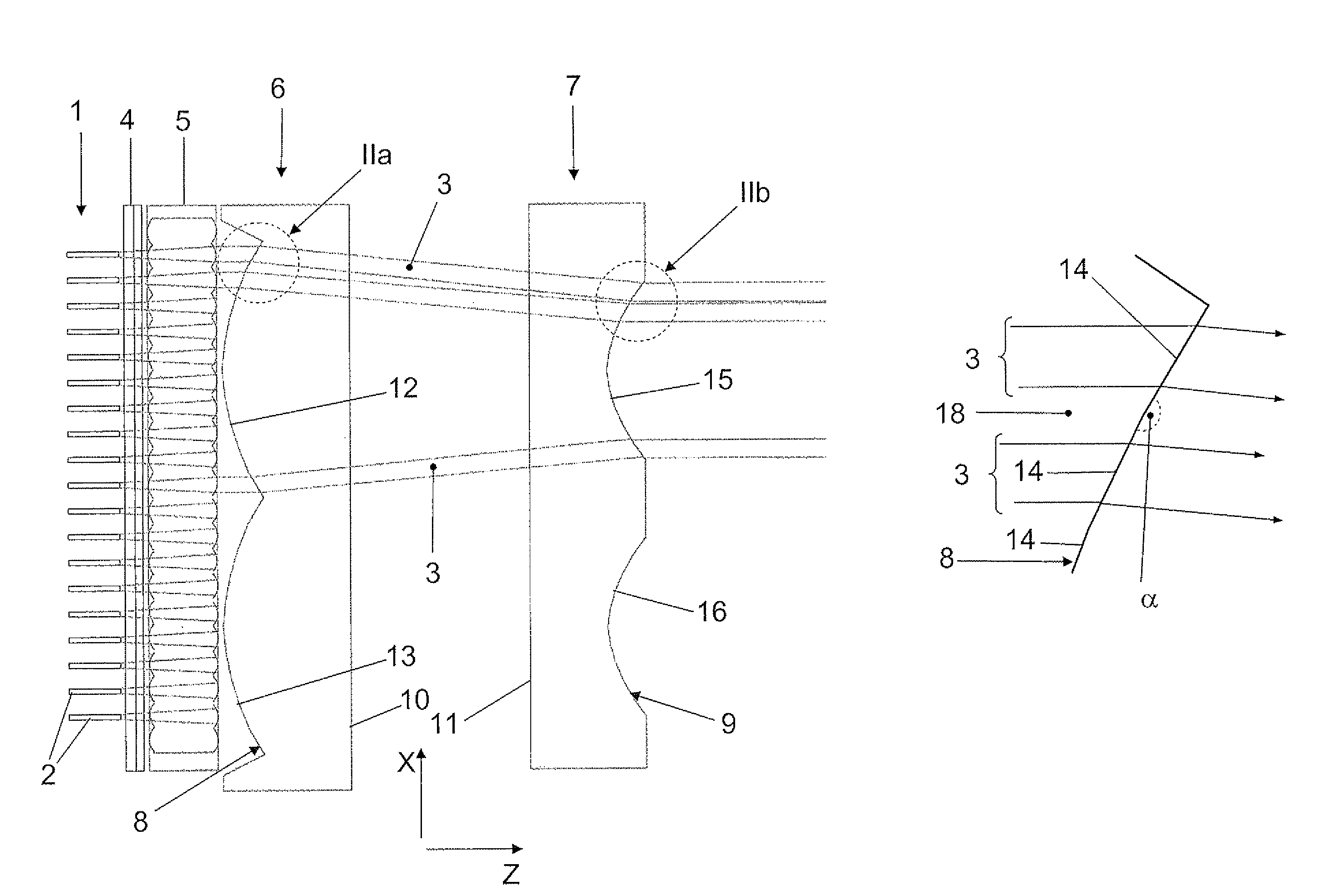
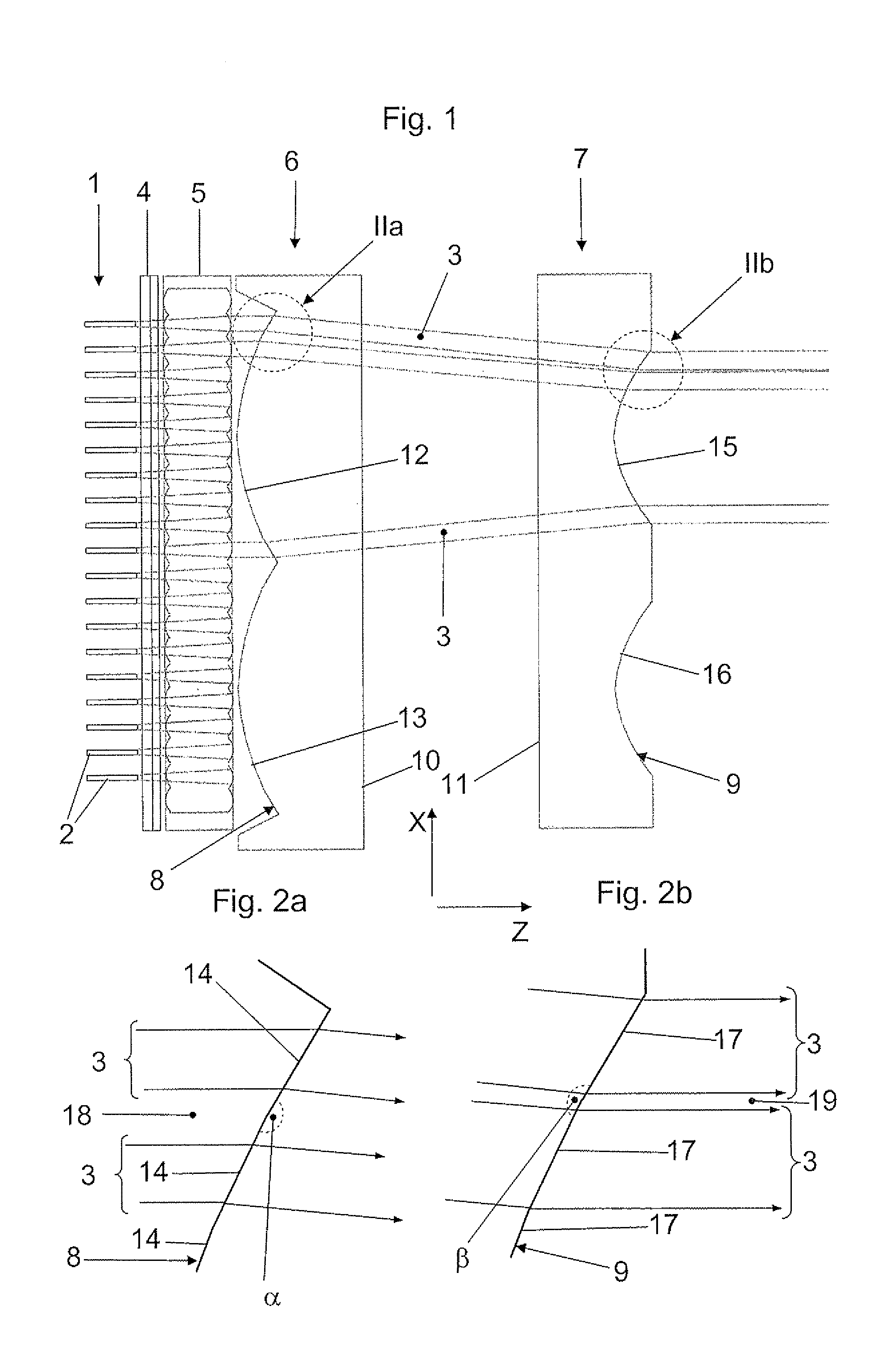
[0032]In the figures, Cartesian coordinate systems are indicated for better guidance.

[0033]In FIG. 1, the reference 1 denotes a laser diode bar and the reference 2 denotes the individual emitters of the laser diode bar 1, which are arranged is spaced apart next to one another in the so-called slow axis i.e. the X direction in the figures. For example, each of the emitters 2 has a length of about 150 μm in the slow axis, the distance between two neighboring emitters 2 in this direction being about 400 μm. The individual emitters 2 emit sub-beams 3 of the laser radiation of the laser diode bar 1.

[0034]The embodiment of a device according to the invention, which may be seen in FIG. 1, comprises a fast-axis collimation lens 4 behind the emitters 2 in the propagation direction Z, which collimates the individual sub-beams 3 in the so-called fast axis i.e. the Y direction in the figures.

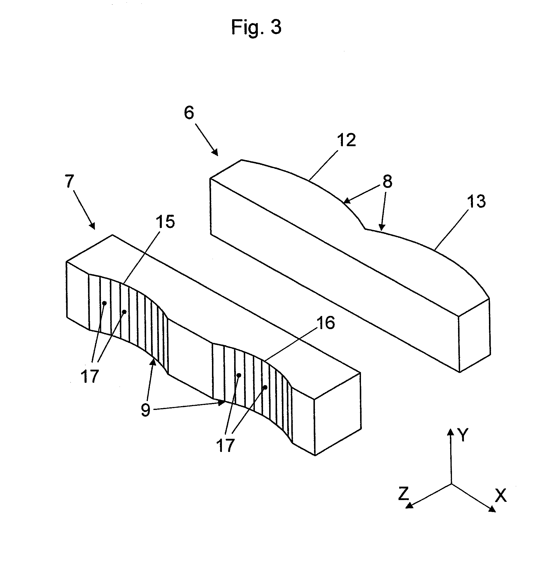
[0035]Behind the fast-axis collimation lens 4 in the propagation direction Z, a beam transformation devi...


PUM


Abstract

Device for shaping laser radiation which has sub-beams (3) spaced apart in a first direction (X) perpendicular to the propagation direction (Z) of the laser radiation, in particular for shaping laser radiation which is output by a laser diode bar (1), comprising a first refractive interface (8) which can differently deviate at least a multiplicity of the sub-beams (3) of the laser radiation to be shaped, so that they travel at least partially converging together after passing through the first interface (8) more than before passing through the first interface (8), and furthermore comprising a second refractive interface (9) through which the laser radiation can pass after having passed through the first interface (8), the second interface (9) being able to deviate at least some of the sub-beams (3) so that their convergence is reduced.

Description

BACKGROUND OF THE INVENTION[0001](1) Field of the Invention[0002]The present invention relates to a device for shaping laser radiation which has sub-beams spaced apart in a first direction perpendicular to the propagation direction of the laser radiation, in particular for shaping laser to radiation which is output by a laser diode bar.[0003]Definitions: in the propagation direction of the light to be influenced means the average propagation of the light, particularly when it is not a plane wave or is at least partially convergent or divergent. Light beam, sub-beam or beam, unless expressly indicated otherwise, does not mean an idealized ray of geometrical optics but a real light beam, for example a light beam with a Gaussian profile, which has an extended rather than infinitesimally small beam cross section.[0004]Laser diode bars have a multiplicity of emitters, for example 19 emitters, which are arranged spaced apart in the so-called slow axis. The slow axis is the aforementioned ...

Claims


Application Information

Patent Timeline
Patent Type & Authority Patents(United States)
IPC IPC(8): G02B27/10
CPCG02B27/0966G02B19/0014G02B19/0057
Inventor BARTOSCHEWSKI, DANIEL
Owner LIMO GMBH
Why Eureka
Try Eureka