Ultrasonic measuring unit having integrated humidity analysis

a technology of humidity analysis and ultrasonic measurement, which is applied in the direction of volume/mass flow measurement, measurement devices, instruments, etc., to achieve the effect of precise engine control, precise metering of fuel, and precise detection of air quantity

Inactive Publication Date: 2011-08-02
ROBERT BOSCH GMBH
View PDF15 Cites 18 Cited by
  • Summary
  • Abstract
  • Description
  • Claims
  • Application Information

AI Technical Summary

Benefits of technology

[0007]The approach proposed according to the exemplary embodiments and / or exemplary methods of the present invention allows extremely precise detection of the air quantity flowing into the intake system of motor vehicle internal combustion engines, so that precise engine control, i.e., very precise metering of fuel to the combustion chambers of the multicylinder internal combustion engine, may be performed. It is thus ensured that the currently applicable emission standards and the stricter emission standards to be expected in the future may be maintained.
[0011]The advantages of two different temperature measuring methods may advantageously be unified by the method described above. These advantages are that, on the one hand, the humidity independence of the otherwise slow temperature probe, which is implemented as an NTC element, for example, may be combined with the rapidity and freedom from contact of an ultrasonic temperature signal, which is otherwise dependent on the humidity. Unifying the cited advantages within a single probe and / or sensor and / or the analysis downstream therefrom results in significantly more precise mass flow and temperature signals than in the related art and in an additional humidity signal which may be processed inside the engine control unit.
[0012]The general advantage of the use of the ultrasonic flow measurement may primarily be seen in the fact that this technology only has a slight drift in the event of contamination, i.e., the ultrasonic signals are only influenced slightly in regard to their plausibility and true validity by contaminants in comparison with other measurement technologies. In addition to the flow rate of the gaseous medium in the flow tube, its speed of sound may also be detected by an ultrasonic run-time measurement. The speed of sound of the gaseous medium is essentially a function of the temperature and the atmospheric humidity. Detecting the speed of sound thus allows a very rapid conclusion regarding the temperature and / or the atmospheric humidity. In contrast to a measurement using a temperature probe, an ultrasonic temperature measurement is completely decoupled from the temperature of the tube wall of the flow tube.

Problems solved by technology

The DE 42 37 907 A1 document has the disadvantage that, if the ultrasonic transducer fails, only an at least approximate measurement of the mass flow rate is performed via the thermal sensor, which results in imprecise results for exactly determining the charge of combustion air in the combustion chambers of an internal combustion engine.

Method used


Image

  • Ultrasonic measuring unit having integrated humidity analysis
  • Ultrasonic measuring unit having integrated humidity analysis
  • Ultrasonic measuring unit having integrated humidity analysis

Examples


Embodiment Construction

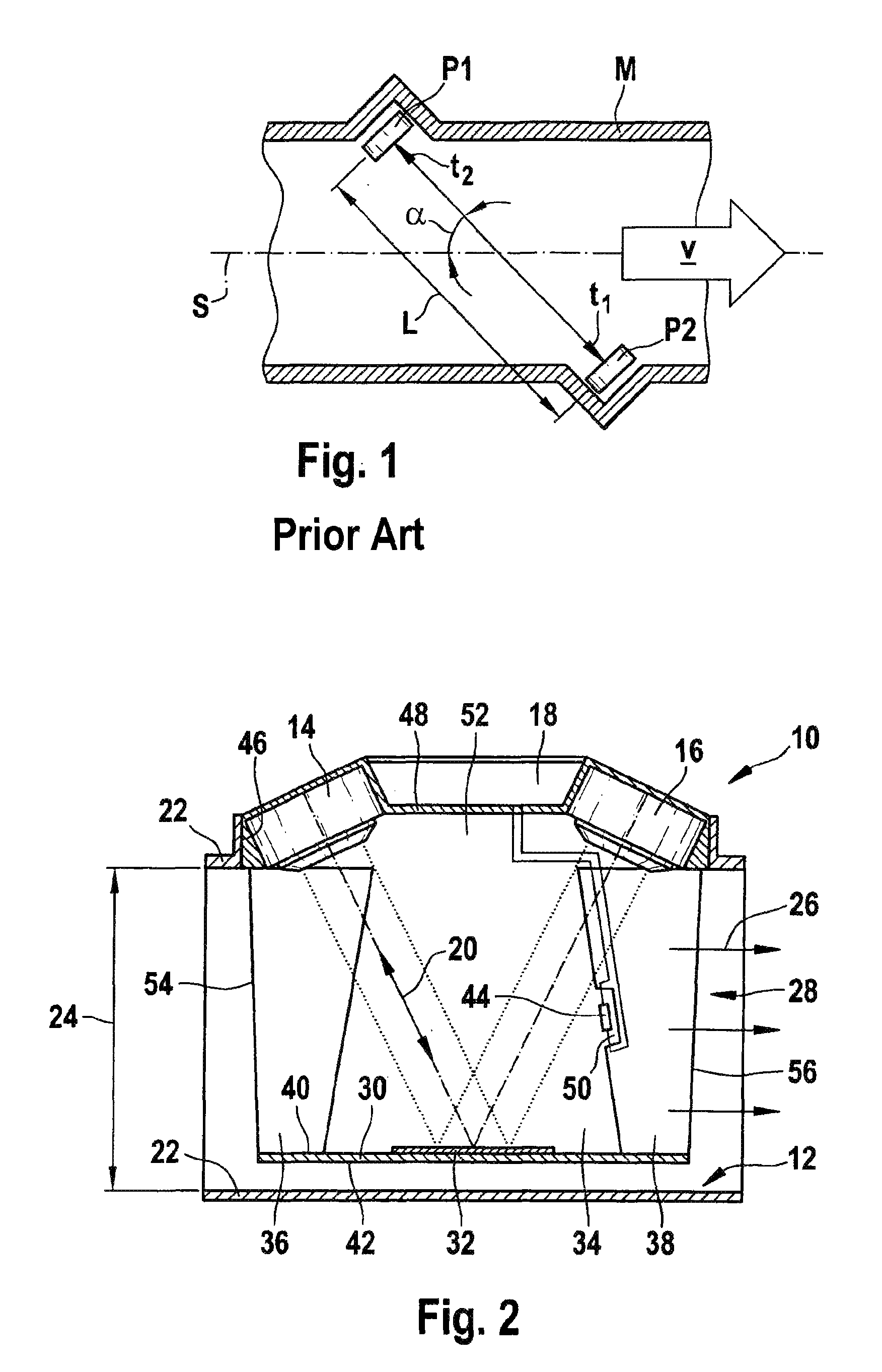
[0017]An ultrasonic flow rate measuring unit from the related art is shown in the illustration in FIG. 1. A first ultrasonic transducer P1 and a second ultrasonic transducer P2 are accommodated diametrically opposite one another in a flow tube M. For this purpose, openings are provided in flow tube M, into which first ultrasonic transducer P1 and second ultrasonic transducer P2 are introduced. According to the illustration in FIG. 1, the distance between first ultrasonic transducer P1 and second ultrasonic transducer P2 is identified by L. Both first ultrasonic transducer P1 and also second ultrasonic transducer P2 are situated tilted by angle α to axis of symmetry S of flow tube M. Medium v flowing in flow tube M flows in the direction of the arrow drawn in FIG. 1. First ultrasonic transducer P1 and second ultrasonic transducer P2 reciprocally transmit and receive ultrasonic signals. A run-time difference is determined from the run-times obtained for the ultrasonic signals in the f...


PUM


Abstract

An ultrasonic measuring unit and a method for detecting ultrasonic signal run-times, in which the ultrasonic measuring unit has two ultrasonic transducers for coupling ultrasonic signals into a flowing medium. Analysis electronics are provided to be accommodated on or in a flow tube, in which a gaseous medium such as circulating air flows. A probe unit is accommodated in the flow tube, the probe unit being assigned a temperature probe having a flow around it, whose measured value is used for correcting a temperature signal detected by ultrasound.

Description

FIELD OF THE INVENTION[0001]The present invention relates to an ultrasonic measuring unit having integrated humidity analysis, in particular for air mass measurement on internal combustion engines.BACKGROUND INFORMATION[0002]A method for measuring the temperature of a fluid in a measuring tube is known from DE 44 42078 A1. According to this method, a first ultrasonic signal is emitted into a measuring tube in the direction of flow of the fluid and received, run-time Tdown of the first ultrasonic signal being measured. Furthermore, a second ultrasonic signal is emitted into the measuring tube against the direction of flow of the fluid and received, run-time Tup of the second ultrasonic signal being measured. Flow velocity v of the fluid in the measuring tube is ascertained from both run-times Tdown and Tup. Flow velocity v of the fluid is determined from speed of sound C0, and temperature T of the fluid flowing in the measuring tube is concluded from speed of sound C.[0003]A mass flo...

Claims


Application Information

Patent Timeline
Patent Type & Authority Patents(United States)
IPC IPC(8): G01F1/66
CPCG01F1/662G01F5/00G01F1/668G01F15/18
Inventor KONZELMANN, UWELANG, TOBIAS
Owner ROBERT BOSCH GMBH
Why Eureka
Try Eureka