Surgical robotic system

a robotic system and robotic technology, applied in the field of surgical robotic systems, can solve the problems of unfavorable patient safety, unfavorable patient safety, and inability to use the end effector, and achieve the effects of high reduction ratio, simple and compact design of the end effector, and high reduction ratio

Active Publication Date: 2011-08-02
DEUTSCHES ZENTRUM FUER LUFT & RAUMFAHRT EV
View PDF14 Cites 135 Cited by
  • Summary
  • Abstract
  • Description
  • Claims
  • Application Information

AI Technical Summary

Benefits of technology

[0014]The hydraulic design of the actuator makes it possible, by very simple constructional means, to realize a very high reduction ratio from 1:10 to more than 1:100. Thus, very high reduction ratios can be obtained through a very simple, compact design of the end effector. In spite of the high forces which thus can be transmitted to the respective end effector element, the hydraulic pressure required for this purpose in the hydraulic line is relatively small. As a result, large pulling or pressure forces transmitted by the hydraulic cylinder to the end effector element will cause only small changes of length of the hydraulic line.
[0015]Preferably, the cross-sectional area of the hydraulic cylinder is at least ten times the cross-sectional area of the hydraulic line. The reduction ratio will thus amount to at least 1:10. Consequently, the axial forces in the shell of the hydraulic line will be no more than one tenth of the drive force transmitted by the hydraulic cylinder to the end effector element. The larger the reduction ratio is, i.e. the smaller the cross-sectional area of the hydraulic line is relative to the cross sectional area of the hydraulic cylinder, the better the mechanical decoupling will be.
[0017]According to a preferred embodiment, the hydraulic cylinder is formed by a closed metallic bellows. The sealing means in hydraulic cylinders have to allow for smooth-running operation on the one hand and must offer absolute leak-tightness on the other hand. Under the effect of the sterilization process required in human medicine, such seals will be damaged over time so that their functional integrity cannot be guaranteed permanently. By contrast, a closed metallic bellows used as a hydraulic cylinder will not need any sealing means and will hermetically close the fluid space against the environment in a reliable manner.

Problems solved by technology

The Bowden cables are occasionally required to transmit considerable pulling and pushing forces.
Even in cases of a highly sophisticated construction, the driving forces transmitted by the Bowden cables will at least partially interfere with the contact forces.
The reason for this effect resides, inter alia, in that the occurrence of axial pulling or pushing forces will inevitably cause a stretching or shortening of the sheath of the Bowden cable, with the unavoidable consequence that undesired driving forces are inserted into the end effector.
Due to manufacturing tolerances and due to the properties of the materials used in miniaturized mechanics, a friction- and loss-free transmission of forces, e.g. via Bowden cables, cannot be guaranteed anymore or can at best be guaranteed only with considerable difficulties.
Further, concerning the mechanical transmission of the driving forces, production and assembly of the mechanics are getting increasingly difficult and complex because of the continuing progress in miniaturization.
As a result, large pulling or pressure forces transmitted by the hydraulic cylinder to the end effector element will cause only small changes of length of the hydraulic line.
Under the effect of the sterilization process required in human medicine, such seals will be damaged over time so that their functional integrity cannot be guaranteed permanently.

Method used


Image

  • Surgical robotic system
  • Surgical robotic system

Examples


Embodiment Construction

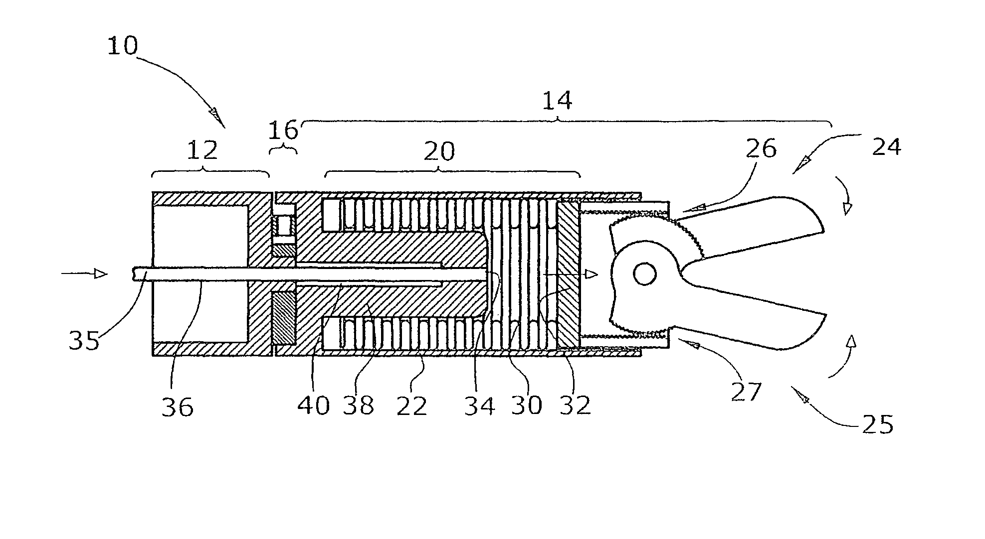
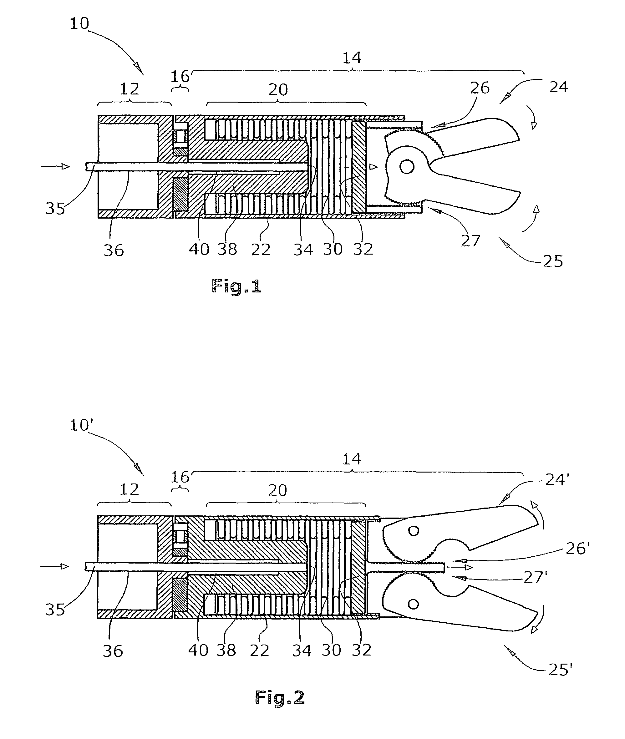
[0024]FIGS. 1 and 2 each illustrate a surgical robotic system 10 and respectively 10′, said system forming a part of a surgical robot for use in minimal-invasive surgery. Each of the surgical robotic systems 10,10′ shown in the Figures comprises a movable robotic arm 12 and an end effector 14 movably fastened to robotic arm 12. End effector 14 is fastened to robotic arm 12 via a force sensor 16 configured as a force / moment sensor with six arms.

[0025]End effector 14 comprises a hydraulic cylinder 20, a housing 22, two pivotable end effector elements 24,25 and toothed-rack drives 26,27; 26′,27′, each of the latter being assigned to a respective one of the end effector elements 24,25. The outer diameter of end effector 14 is 5 to 15 mm.

[0026]Hydraulic cylinder 20 is formed by a metallic bellows 30, a closure piston 32 and a hydraulic-line opening 34 of hydraulic line 36. Hydraulic line 36 has an internal cross-sectional area of about 0.2 mm2. Said bellows 30 and respectively said hydra...


PUM


Abstract

A surgical robotic system includes a robotic arm, an end effector movably connected thereto and provided with a movable end effector element driven by an actuator, and a force sensor arranged between the robotic arm and the end effector. The actuator is formed by a hydraulic cylinder. The robotic arm is provided with a hydraulic line connected to said hydraulic cylinder of the end effector.

Description

BACKGROUND[0001]1. Field of the Disclosure[0002]The present disclosure relates to a surgical robotic system comprising a robotic arm with an end effector attached thereon.[0003]2. Discussion of the Background Art[0004]In the field of minimal-invasive surgery, use is made of surgical robots as surgical instruments for performing e.g. gripping and cutting processes in the patient's body. For this purpose, a surgical robotic system comprises a robotic arm and, at the end of the robotic arm, an end effector including a movable end effector element. Said end effector element can be e.g. a forceps or a pair of scissors. On the end effector, an actuator is provided for moving the end effector element such as, e.g., an arm of a forceps.[0005]Arranged between the end effector and the robotic arm is a force sensor for detection of the forces externally acting on the end effector, particularly of the gripping forces and the contact forces. Gripping forces are defined as the forces which are ge...

Claims


Application Information

Patent Timeline
Patent Type & Authority Patents(United States)
IPC IPC(8): B25J15/02
CPCA61B19/22F15B15/10A61B19/2203Y10T74/20329A61B2019/464A61B2017/00539A61B34/30A61B34/70A61B2090/064
Inventor SEIBOLD, ULRICH
Owner DEUTSCHES ZENTRUM FUER LUFT & RAUMFAHRT EV
Why Eureka
Try Eureka