Wind turbine with adjustable airfoils

a technology of wind turbines and airfoils, which is applied in the direction of rotors, greenhouse gas reduction, vessel construction, etc., can solve the problems of affecting the power generation ability of wind turbines, affecting the efficiency of wind turbines, so as to achieve robust and durable effects

Inactive Publication Date: 2011-08-09
HEID TOM
View PDF7 Cites 11 Cited by
  • Summary
  • Abstract
  • Description
  • Claims
  • Application Information

AI Technical Summary

Benefits of technology

The screw motor can be understood to regulate the distance D between the centers of the trailing edge adjustment hub and the carousel and thereby regulate the size of the angle gamma. That ability is critical for obtaining maximum performance of the wind turbine of the present invention. At start-up those of skill will understand that a large positive gamma is desirable to create an amount of aerodynamic drag whereby sufficient torque can be exerted against the airfoils to initiate rotation, particularly in a low wind condition. Once sufficient rotational speed is achieved, the angle gamma can be reduced to reduce drag and permit increased rotational speed.
It will be appreciated that the present invention has a number of advantages over the prior art. The adjustment mechanism being housed between the trailing edge adjustment hub and the upper carousel or leading edge hub serves to protect those components from the deleterious effects of weather. Additionally, that approach combined with the particular connection of the rudder to the adjustment shaft provides for a vertically compact mechanism and also one that is robust and durable.

Problems solved by technology

However, in order to achieve efficient operation a HAWT is desirably mounted on a high tower to lift it and the blades thereof above air obstructions that create turbulent or obstructed wind flow that hinder its performance.
The rotating shaft typically couples a generator to a gear box, both mounted to the tower and hence difficult to install and service.
VAWT's therefore hold out the possibility of providing a lower cost wind power alternative and for areas where an HAWT would not be suitable due to lower than required average wind speeds.
However, in VAWT's of the Savonius type the blades only produce power during half of their rotation and fight against the wind during the return half thereof.
Thus, such VAWT's can not rotate at a speed greater than the wind speed thereby severely limiting their ability to harvest power from the available wind.
A Darrieus or “eggbeater” type VAWT's are known that produce power in both directions, but suffer from the fact that they often need assistance to get their rotation started.
Frequently the vanes are designed to provide adequate torque to provide for self start-up at zero rotational velocity, but due to their inherent large amount of drag are limited in the peak attainable velocity.
However, a major problem therewith concerns the cost, complexity, increased maintenance and reduction of generation efficiency that result from the mechanisms that exist to provide for such airfoil adjustment.

Method used


Image

  • Wind turbine with adjustable airfoils
  • Wind turbine with adjustable airfoils
  • Wind turbine with adjustable airfoils

Examples


Embodiment Construction

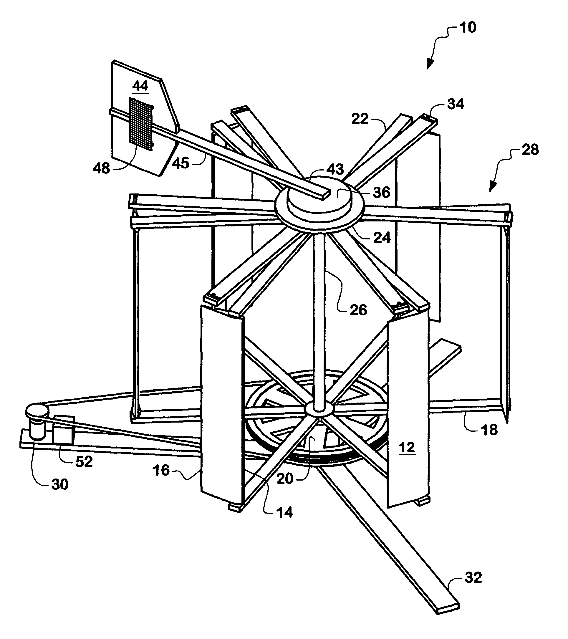
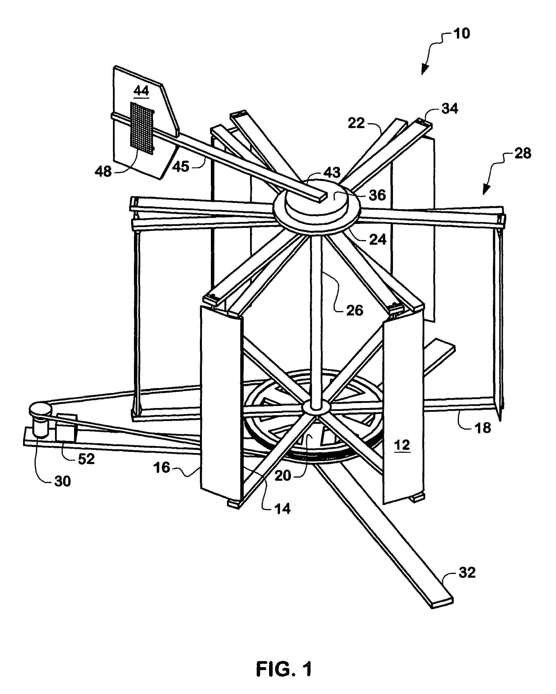
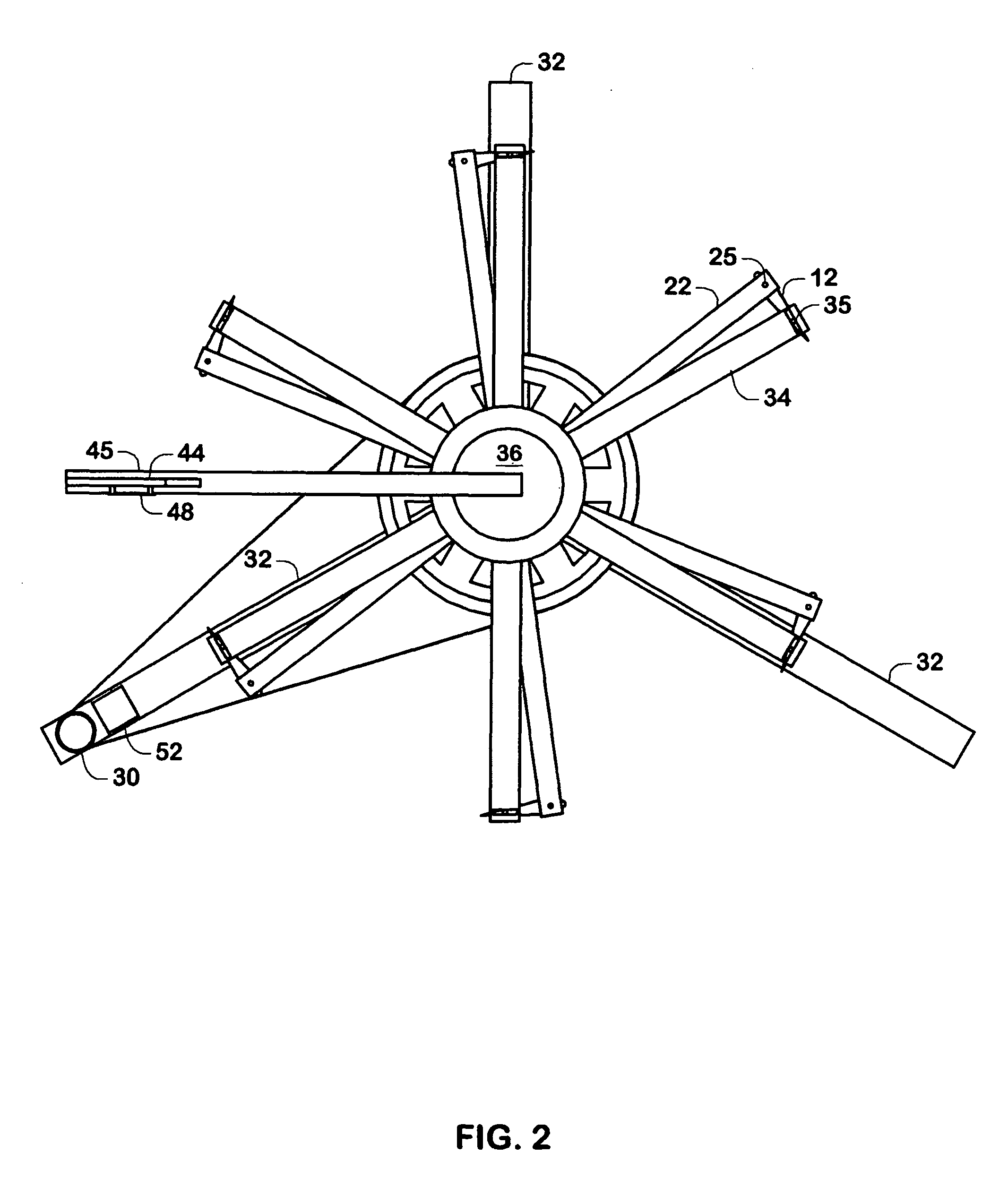
As seen by referring to FIGS. 1 and 2, the wind turbine of the present invention is shown and generally referred to by the numeral 10. Turbine 10 includes a plurality of vertically extending airfoils 12 each having a leading edge 14 and a trailing edge 16. Each airfoil 12 is pivotally secured at its leading edge 14 on a bottom end thereof to spoke arms 18 extending from a lower central hub 20. The top ends of airfoils 12 are also pivotally secured at top ends thereof to the same point there along at the leading edge 14 to the ends of upper spoke arms 22 extending from an upper central hub 24. Specifically as seen in FIG. 3, each arm spoke 22 includes a hole 23 for insertion therein of a pin 25 extending from its corresponding airfoil 12 to provide for the stated pivotal connection there between. Additionally, a spring return mechanism includes a spring 27 extending around pin 25 and retained on one end thereof in a hole 27a of arm 22 and a hole 27b of airfoil 12.

A central vertically...


PUM


Abstract

The present invention concerns a wind turbine having a plurality of vertically extending airfoils forming a rotating carousel rotating about a central axis thereof. The airfoils pivot about their leading edges to adjust the pitch angle thereof to maximize energy harvest when the airfoils are rotating both in an upwind direction and in a down wind direction. This pivoting movement results from trailing edges of the airfoils being pivotally secured to rigid spokes or cables of a trailing edge hub. An adjustment mechanism is pivotally mounted between a carousel hub and the trailing edge hub and is used to control the separation between a central axis of the trailing edge hub and the axis of rotation of the carousel as they co-rotate. As the carousel rotates, the offset distance between the two axes determines the maximum achievable pitch angle of each airfoil. The airfoils then continually cycle between a positive and negative value of the maximum pitch angle so that each airfoil is at its most desirable pitch angle relative to its position around the carousel and relative to the existing wind direction in order to create maximum lift. A wind direction rudder is secured to the adjustment mechanism to provide for movement thereof resulting in movement of the trailing edge hub as wind direction changes so that the most desirable pitch angle of the airfoils relative to wind direction is maintained.

Description

FIELD OF THE INVENTIONThe present invention relates generally to wind powered energy generating devices and in particular to wind power generating devices of the vertical axis airfoil type.BACKGROUND OF THE INVENTIONWind turbines used to generate electrical power are well known in the art and can be divided into two main categories relative to their axis of rotation. Thus, vertical axis wind turbines (VAWT's) have a plurality of blades or airfoils rotating about a vertically extending axis and horizontal axis wind turbines (HAWT's) having the blades or “propellers” thereof rotating about a horizontally extending axis. There exist advantages and disadvantages with each type. Current art HAWT's are generally more efficient at extracting electrical power from a given wind current, where for example, large wind generators in the megawatt range are exclusively of the horizontal type. However, in order to achieve efficient operation a HAWT is desirably mounted on a high tower to lift it a...

Claims


Application Information

Patent Timeline
Patent Type & Authority Patents(United States)
IPC IPC(8): F03D7/06
CPCF03D3/068F03D7/06F05B2260/50F05B2260/70F05B2260/72Y02E10/74
Inventor ANDERSON, DONALD E.CHRISTIAN, DANIEL W
Owner HEID TOM
Why Eureka
Try Eureka