Apparatus for use in operator training with, and the testing and evaluation of, infrared sensors which are for missile detection

a technology for infrared sensors and operators, applied in the direction of optical radiation measurement, instruments, semiconductor lasers, etc., can solve the problems of inability to operate in practicable conditions, thermal management problems, and limited use of infrared illumination sources such as lamps or thin filaments

Active Publication Date: 2011-08-16
TEXTRON SYST
View PDF14 Cites 5 Cited by
  • Summary
  • Abstract
  • Description
  • Claims
  • Application Information

AI Technical Summary

Benefits of technology

[0015]1. Infrared missile detection sensors being tested respond only to a very narrow band of wavelengths. Infrared illumination sources currently used emit energy over a very broad band of wavelengths. The use of the pseudo continuous wave laser infrared illumination source offers a much greater in-band power output within a given aperture, for a given input power, resulting in highly efficient emitter apparatus.
[0016]2. The pseudo continuous wave laser infrared illumination source has lower electrical power supply requirements than known currently used infrared illumination sources. Thus the apparatus of the present invention has low power control requirements in terms of switching, and thereby considerably less electromagnetic compatibility issues than is the case for known and currently used infrared illumination sources.
[0018]4. Pulsed lasers sources are available over a broad range of infrared wavelengths, such that the spectral characteristics of the illumination source can be tuned to specific applications efficiently. This could include use of more than one source to generate a complex spectrum. This is especially pertinent for infrared detectors which use spectral characteristics as a discriminator for determining the veracity of the illumination source.
[0020]6. The pseudo continuous wave laser infrared illumination source can approximate point sources and optical components can be designed to optimise the beam forming for a specific application, maximising boresight power for any given beam width.

Problems solved by technology

In the above mentioned known apparatus, the use of infrared illumination sources such for example as the lamps or the thin filaments has proved to be a limiting factor in the generation of high powers in the mid-infrared wavelength range of 3-5 μm.
More specifically, problems associated with the known apparatus using the lamps or the thin filaments are as follows.1. High input power requirements for high power sources.2. Attempts to reduce out of band wavelengths may lead to thermal management issues.3. The generation of wavelengths which extend beyond the required infrared band can result in impractical operating conditions due to the wavelengths generated, such impractical operating conditions including those relating to eye safety and to covertness of source.4. The beam width in any illumination system is limited by the source extent and by aperture constraints.
However, beam widths much greater than 3° obtained with existing infrared illumination sources may result in a lower power density across the intended target.5. Modulation capabilities of heated lamps and filaments are limited.
These modulation capabilities are adequate for present day infrared missile detection sensors but they generally do not have the capacity for future developed infrared missile detection sensors.6. High electromagnetic emissions, which are related to normal operation and the infrared illumination source being modulated, may be generated at problematic magnitudes.
This is especially a problem for infrared illumination sources in the form of lamps.7. The known infrared illumination sources cannot generate sufficient infrared power within aperture limitations which apply.
These aperture limitations are dictated by the need to present a realistic source extent to the sensor, for example when mounted on an aircraft.

Method used


Image

  • Apparatus for use in operator training with, and the testing and evaluation of, infrared sensors which are for missile detection
  • Apparatus for use in operator training with, and the testing and evaluation of, infrared sensors which are for missile detection
  • Apparatus for use in operator training with, and the testing and evaluation of, infrared sensors which are for missile detection

Examples


Embodiment Construction

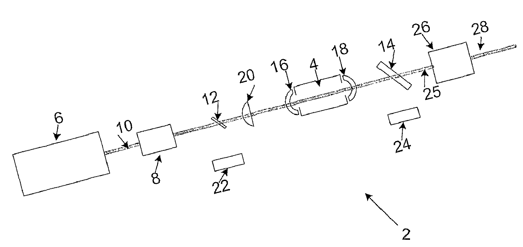
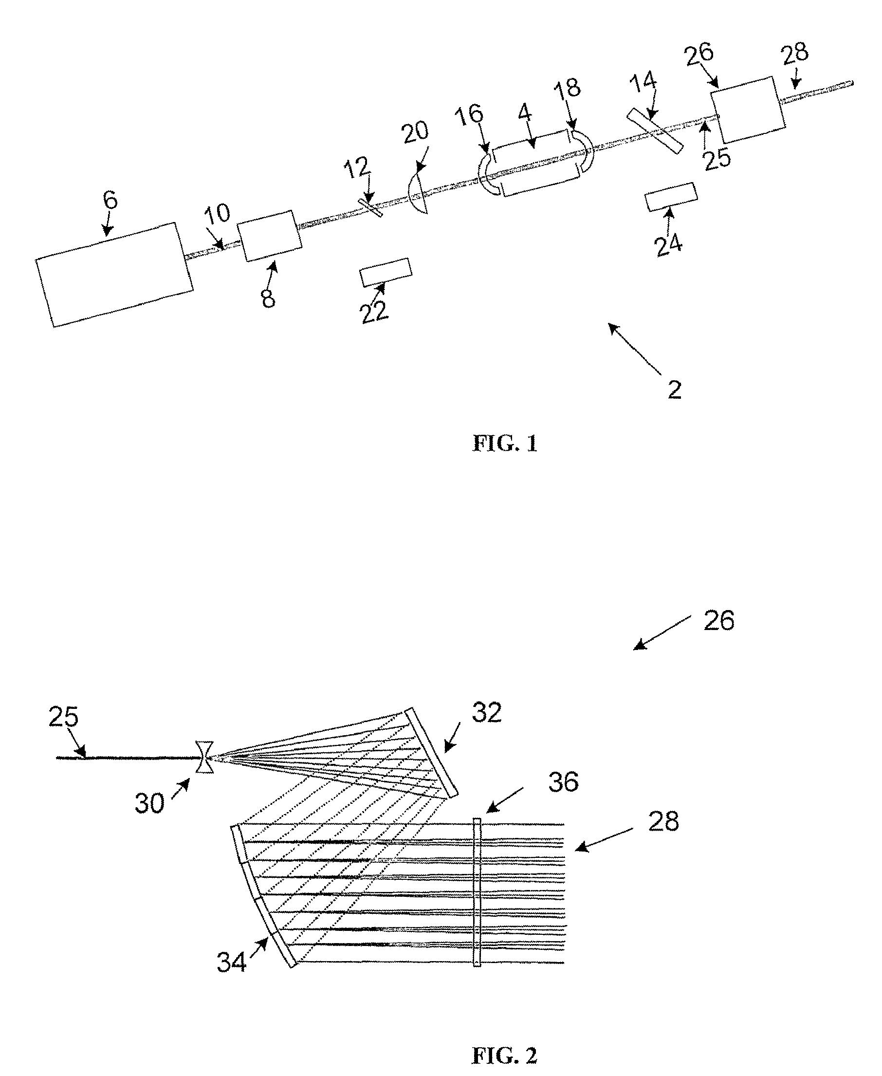
[0036]Referring to FIGS. 1 and 2, there is shown apparatus 2 for use in the testing and evaluation of infrared sensors which are for missile detection and which integrate incident energy over a finite time period, according to an exemplary embodiment of the invention. The apparatus 2 comprises at least one infrared illumination source for illuminating the sensors. The infrared illumination source is in the form of a pseudo continuous wave laser infrared illumination source with signal duty and peak power controlled by means of an amplitude, pulse width and pulse repetition interval modulation circuit, whereby the infrared illumination source operates at shorter repetition intervals than the finite time period so that the laser infrared illumination source appears to the infrared sensors to be a missile signature. The laser infrared illumination source is an optical parametric oscillator 4, which is pumped by a laser 6. The laser 6 is a yttrium aluminium garnet (YAG) laser.

[0037]The ...


PUM


Abstract

Apparatus (2) for use in operator training with, and the testing and evaluation of, missile detection systems which use infrared sensors which integrate incident energy over a finite time period, which apparatus (2) comprises at least one infrared illumination source (4) for illuminating the sensors, characterised in that the infrared illumination source (4) is a pseudo continuous wave laser infrared illumination source (4) with signal duty and peak power controlled by means of an amplitude, pulse width and pulse repetition interval modulation circuit (8), whereby the laser infrared illumination source (4) operates at shorter repetition intervals than the finite time period so that the laser infrared illumination source (4) appears to the infrared sensors to be a real missile signature.

Description

CROSS-REFERENCE TO RELATED APPLICATIONS[0001]This application is the national phase under 35 U.S.C.§371 of PCT / IB2007 / 000994 filed Apr. 17, 2007, which claims priority to Great Britain Application No. 0607655.8 filed Apr. 18, 2006, the subject matter of both is incorporated herein by reference in its entirety.BACKGROUND OF THE INVENTION[0002]This invention relates to apparatus for use in operator training with, and the testing and evaluation of, infrared sensors for missile detection. More especially, this invention relates to apparatus for use in the testing and evaluation of infrared sensors which are for missile detection and which integrate incident energy over a finite time period.[0003]Apparatus is known for use in operator training with, and the testing and evaluation of, infrared sensors for missile detection. The known apparatus comprises an infrared illumination source for illuminating the sensors. The infrared illumination source may be a lamp such for example as a xenon ...

Claims


Application Information

Patent Timeline
Patent Type & Authority Patents(United States)
IPC IPC(8): G01J5/10
CPCB82Y20/00F41G7/004F41G7/224H01S5/005H01S5/0085H01S5/3402H01S5/4031F41J2/02
Inventor STANIFORTH, MICHAEL JUSTINJAMES, GRAHAM EDWARDHOLLOWAY, STEPHEN
Owner TEXTRON SYST
Why Eureka
Try Eureka