
Low-fuel-consumption transport ship

a technology of low-fuel consumption and transport ships, which is applied in the field of low-fuel consumption transport ships, can solve the problems of not negligible air resistance, difficult to decrease both air resistance and underwater resistance, and no countermeasures have been made concerning transport ships. , to achieve the effect of reducing air resistance, facilitating operation, and cancelling underwater resistan

Active Publication Date: 2011-08-23
MITSUI TETSUO +1
View PDF3 Cites 1 Cited by
  • Summary
  • Abstract
  • Description
  • Claims
  • Application Information

AI Technical Summary

Benefits of technology

"The present invention is a low-fuel-consumption transport ship designed to save energy while maintaining its function of holding cargoes. It achieves this by decreasing the air resistance and the underwater resistance of the ship. The bow portion is formed in a hollow semispherical shape to decrease the air resistance, and a bridge is formed on the upper part of the bow to decrease the underwater resistance. The ship also has a vertical tail with a fixed angle or adjustable angle to cancel out the swinging moment caused by the wind. The invention also provides a symmetrical shape to the vertical tail, which helps decrease the underwater resistance. Overall, the invention reduces the fuel consumption of the ship while maintaining its function of holding cargoes."

Problems solved by technology

However, no countermeasure has heretofore been made concerning the transport ships like pure car carriers, container ships and passenger ships having relatively large structures over the water line and against which the air resistance is not negligible.
This fact means that it is difficult to decrease both the air resistance and the underwater resistance while giving importance to the function for holding cargoes.
The sails, however, are operated unattended; i.e., are automatically operated by using a computer.
Though this ship may have been more advanced than the conventional sailing ships, the deck inevitably has decreased free areas, and it is difficult to find a space for installing a crane.
Therefore, the technology of this non-patent document 1 could not be applied to the PCC or the container ship having large structures over the water line.
Conventional pure car carriers, container ships and passenger ships have structures of relatively large volumes over the water line due to their needs, making it difficult to decrease the air resistance.
Besides, the swinging moment of the hull produced by the air resistance must be corrected by checking the helm inevitably causing an increase in the underwater resistance while traveling.
In the conventional transport ship, it is quite difficult to put the above task into practice.

Method used


Image

  • Low-fuel-consumption transport ship
  • Low-fuel-consumption transport ship
  • Low-fuel-consumption transport ship

Examples


embodiment 1

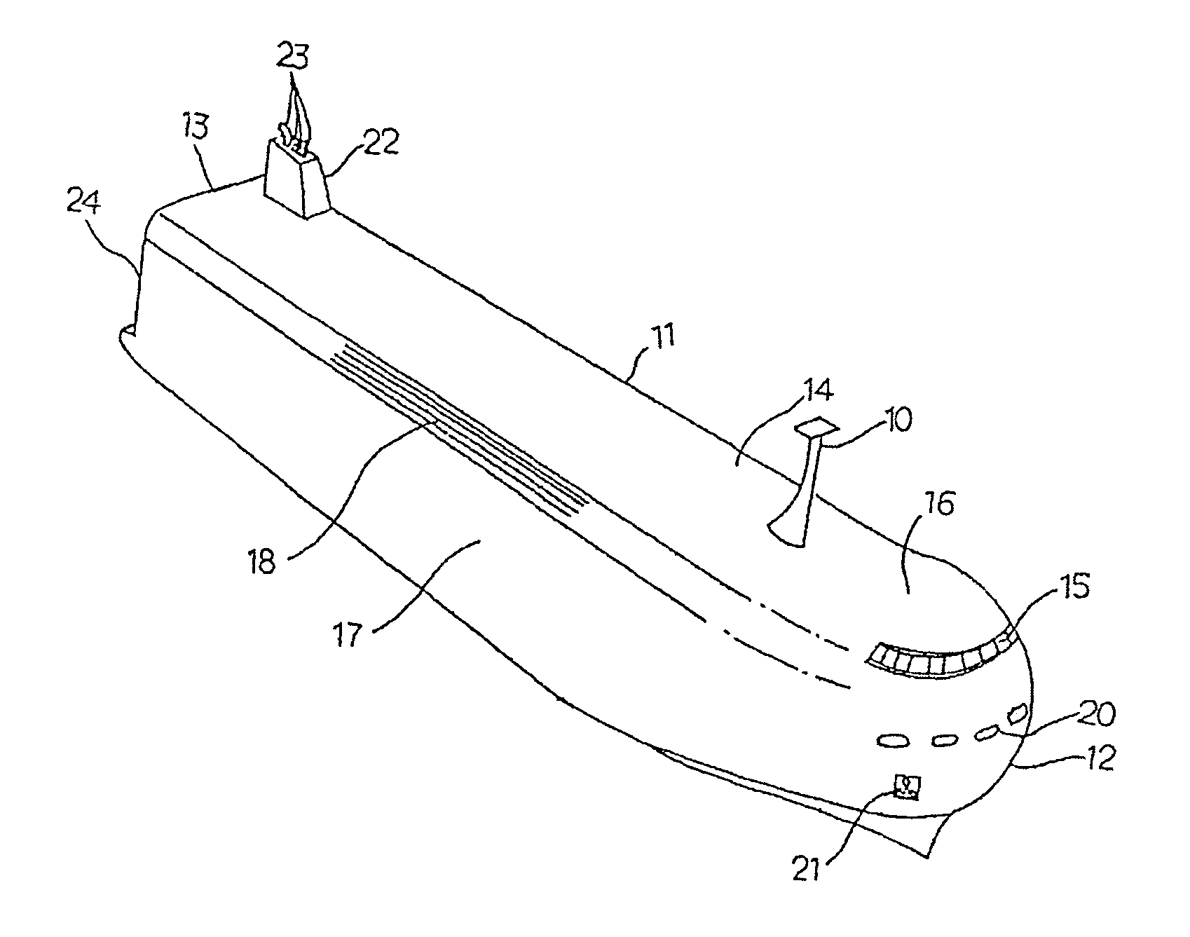
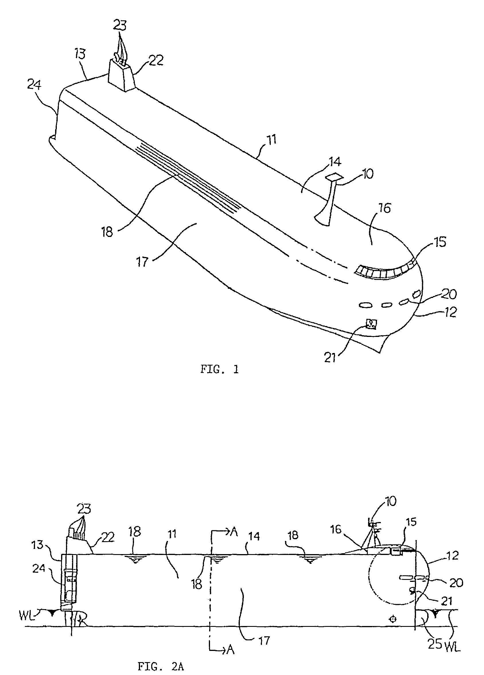
[0043]This embodiment deals with a case where the structure of the invention is applied to a pure car carrier, the structure of the invention being nearly semispherical at the bow and having the same curvature as that of the diameter of the semisphere on both sides of the uppermost deck. FIG. 1 is a perspective view of the hull of the pure car carrier according to the embodiment of the invention and FIG. 17 is a perspective view of the hull of a conventional pure car carrier.

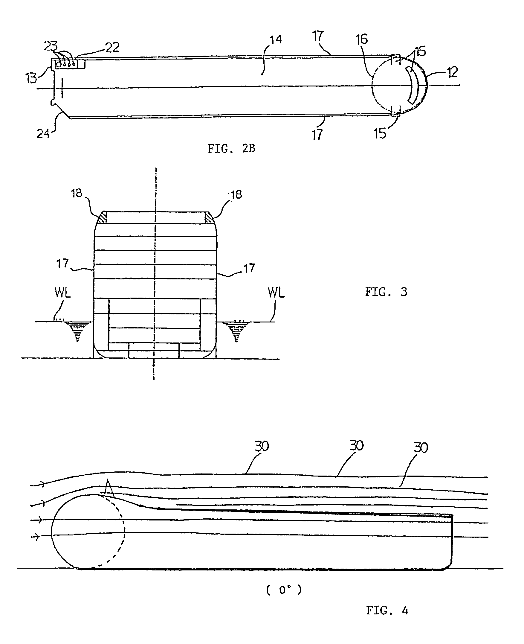
[0044]FIG. 2A is a side view of the bow of the ship of the invention, FIG. 2B is a plan view thereof, and FIG. 3 is a schematic sectional view of when both side portions of the uppermost deck is cut in the direction of width of the ship.

[0045]In the pure car carrier of this embodiment (FIGS. 2A and 2B), the semisphere has its lower end over the water line as viewed from the side surface thereof, and does not cause a change in the shape of the hull under the water level. The upper portion (domed portion) is used ...

embodiment 2

[0081]According to the embodiment of the invention, the flow of air on the uppermost deck forms less exfoliation zone than the prior art. The embodiment which utilizes this nature will now be described dealing with a vertical tail 22A incorporating a chimney 22 nearly in the central portion thereof, and having a leading flap 22B and a trailing flap 23C of which the angles can be adjusted with reference to FIGS. 11, 12 and 17.

[0082]This embodiment deals with a pure car carrier of a structure having a semispherical shape at the bow and a structure of the same curvature as the diameter of the semisphere on both sides of the uppermost deck, being further equipped with the vertical tail that is remotely controlled. FIG. 1 is a perspective view of the pure car carrier of the invention.

[0083]FIG. 11 is a plan view of when the vertical tail of the ship of the invention is provided with the leading flap and the trailing flap of which the angles can be adjusted, and FIG. 12 is a plan view ill...


PUM


Abstract

Transport ships having a relatively large structure over the water line, such as a pure car carrier, container ship and a passenger ship tend to receive the air resistance during the sailing. When sailing aslant against the wind, check helm had to be effected so far to cancel the swinging moment causing an extra increase in the underwater resistance. A low-fuel-consumption transport ship described has a structure over the water line, including a bow of a shape integral with the bridge of a hollow nearly semispherical to quarter-spherical shape or a partly cylindrical shape which is smoothly continuing to the stern to decrease the air resistance. The low-fuel-consumption transport ship further has a vertical tail incorporating a chimney and is rotatable on the uppermost stern deck to cancel the swinging moment in the air, without almost requiring check helm and, therefore, decreasing the underwater resistance.

Description

TECHNICAL FIELD[0001]This invention relates to a low-fuel-consumption transport ship. More specifically, the invention relates to a low-fuel consumption transport ship having a relatively large structure over the water line as represented chiefly by a pure car carrier, a container ship or a passenger ship, which is designed to decrease not only the air resistance but also the underwater resistance.BACKGROUND OF THE INVENTION[0002]A variety of transport ships decreasing the underwater resistance have heretofore been proposed employing improved bulbous shapes at the bows in water and improving the effect correspondingly. However, no countermeasure has heretofore been made concerning the transport ships like pure car carriers, container ships and passenger ships having relatively large structures over the water line and against which the air resistance is not negligible. This fact means that it is difficult to decrease both the air resistance and the underwater resistance while giving ...

Claims


Application Information

Patent Timeline
Patent Type & Authority Patents(United States)
IPC IPC(8): B63B1/16
CPCB63B1/06B63B15/00B63B35/54B63B25/004B63B25/00
Inventor MITSUI, TETSUOKAWAHARA, KENZO
Owner MITSUI TETSUO
Learn More