Liquid crystal display using different light radiation angles of light emitting diodes

a technology of light emitting diodes and liquid crystal displays, which is applied in the manufacture of electric discharge tubes/lamps, lighting and heating apparatuses, instruments, etc., can solve the problems of low space efficiency of illumination, high manufacturing cost, bulky exterior, etc., and achieve low manufacturing cost and less dark areas

Inactive Publication Date: 2011-08-30
SAMSUNG DISPLAY CO LTD
View PDF7 Cites 32 Cited by
  • Summary
  • Abstract
  • Description
  • Claims
  • Application Information

AI Technical Summary

Benefits of technology

Accordingly, it is an aspect of the present invention to provide a backlight assembly with less of a dark area and a compact exterior with a low manufacturing cost by using different radiation angles of different LEDs.
At the corner portion, the second LED may be slanted and, thus, may distribute its emitted light to the LGP more effectively. Namely, the light radiated to the outer area of the LGP can be minimized by placing the second LED at the corner portion of the LGP. With respect to above configuration, accordingly, the dark area of the LGP can be reduced and the whole backlight assembly can be compact.

Problems solved by technology

In an edge light backlight assembly, the LGP has a dark area close to a light incident area due to a limited light radiation angle of the LED and has low space efficiency for illuminating.
Accordingly, an increased number of LEDs or widening radiation angle of each LED may lead to high manufacturing cost, high power consumption and a bulky exterior.

Method used


Image

  • Liquid crystal display using different light radiation angles of light emitting diodes
  • Liquid crystal display using different light radiation angles of light emitting diodes
  • Liquid crystal display using different light radiation angles of light emitting diodes

Examples


Embodiment Construction

Reference will now be made in detail to exemplary embodiments of the present invention, examples of which are illustrated in the accompanying drawings, wherein like reference numerals refer to like elements throughout. The embodiments are described below in order to explain the present invention by referring to the figures.

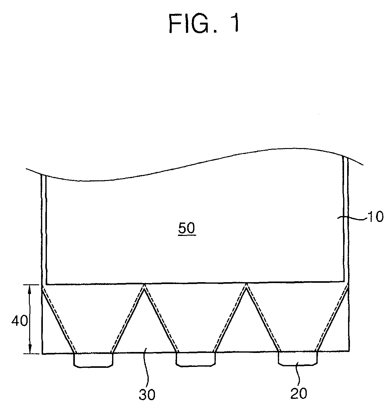
FIG. 1 is a plan view illustrating a dark area of a backlight assembly caused by a plurality of LEDs with the same light radiation angle. According to FIG. 1, the backlight assembly comprises an LGP 10 and a plurality of LEDs 20. Each LED 20 has a light emitting semiconductor chip enclosed by a package and accordingly has a limited light emitting range called light radiation angle 25. In detail, the light emitted from the LED 20 is spread within two edge lines which define the light radiation angle 25.

In FIG. 1, the backlight assembly includes three LEDs 20 whose light radiation angel 25 is 72 degrees. Due to the LEDs' linear arrangement and light radiation angle ...


PUM


Abstract

A liquid crystal display with low manufacturing cost, small dark area and compact exterior is provided by utilizing a plurality of differently radiating light emitting diodes at different angles. The liquid crystal of present invention includes a thin film transistor panel for displaying image, a backlight assembly for providing light to the thin film transistor panel with a plurality of light emitting diodes with different light radiation angles and a light guiding plate, and a frame unit for encompassing the thin film transistor panel and the backlight assembly. The light emitting diodes are placed either at the mid-point of light incident surface or the corner portion of the light guiding plate.

Description

This application claims priority to Korean Patent Application No. 2007-59720, filed on Jun. 19, 2007 and all the benefits accruing therefrom under 35 U.S.C. §119, and the contents of which in its entirety are herein incorporated by reference.BACKGROUND OF THE INVENTION1. Field of the InventionThe present invention relates to a liquid crystal display (LCD) backlight assembly, and more particularly, the present invention relates to a backlight assembly using different radiation angles of different light emitting diodes for low manufacturing cost, compact exterior and luminance efficiency.2. Description of the Related ArtAs display devices are used in everyday life, the liquid crystal display (LCD) has been gaining popularity. The LCD has a thin film transistor (TFT) panel which includes a pair of opposing substrates with a liquid crystal layer therebetween. The LCD also has a backlight assembly since the liquid crystal layer is not self-emissive. The backlight assembly is located behi...

Claims


Application Information

Patent Timeline
Patent Type & Authority Patents(United States)
IPC IPC(8): F21V7/04
CPCG02B6/002G02B6/0068Y10S362/80G02B6/0073G02F1/1335
Inventor WOO, SEUNG-GYUNCHU, YOUNG-BEELEE, IK-SOO
Owner SAMSUNG DISPLAY CO LTD
Why Eureka
Try Eureka