Floating dispenser for dispensing a solid dissolvable chemical into ambient water

a floating dispenser and dissolvable technology, applied in the field of chemical dispensers, can solve the problems of ineffective signaling mechanism, significant hiatus in water treatment, and compromise the aesthetics of the device, and achieve the effects of enhancing the mechanical reliability of the refill indicator, avoiding any significant hiatus in water treatment, and high degree of mechanical reliability

Active Publication Date: 2011-08-30
BIO LAB +1
View PDF18 Cites 11 Cited by
  • Summary
  • Abstract
  • Description
  • Claims
  • Application Information

AI Technical Summary

Benefits of technology

[0007]The dispenser has a refill indicator including a pair of tabs that are connected to a basket disposed in the interior of the bucket that carries a solid, dissolvable water treatment chemical, such as calcium hypochlorite. The tabs are slidably mounted in slots in the top wall. The basket is buoyant and moves upwardly toward the top wall of the bucket upon the dissolution of an amount of water treatment chemical indicative of a refill condition. The tabs extend above the top wall when the buoyant basket floats upwardly toward the top wall, providing a visual indication of the need for a refill that can easily be seen from a side angle. In the preferred embodiment, the basket moves upwardly into engagement with the underside of the top wall when most of a full load amount of water treatment chemical has dissolved, for example 90% of the maximum load capacity of treatment chemical of the basket. The ability of the refill indicator to indicate that a refill condition is imminent before all the water treatment chemical has dissolved advantageously allows the operator to refill the dispenser before it becomes completely empty, thus avoiding any significant hiatus in water treatment.
[0008]The tabs and the slots in the top wall are slidably connected throughout the entire range of movement of the basket within the bucket, thereby providing the refill indicator with a high degree of mechanical reliability. Preferably, the bucket interior and the basket exterior have a non-round shape and a plurality of guide ribs on one that slidably interfit with elongated recesses on the other so as to insure alignment between these two components at all positions of the basket within the bucket, thereby preventing misalignment between tabs and the slots in the top wall and further enhancing the mechanical reliability of the refill indicator.
[0009]The floatation portion of the bucket may include a buoyant material, such as a polymeric foam, that surrounds the upper end of the bucket such that most of the mass of the dispenser below the top wall is submerged, and both the bucket and basket are shaped so that the center of mass of the dispenser is located along a central axis. The resulting buoyancy configuration causes the dispenser to float in a vertical orientation with the top wall always a little above the water line such that the indicator tabs of the refill indicator can always be easily seen, and further allows the dispenser to be self-righting when exposed to waves or other water turbulence.
[0010]The bucket may also include a bottom wall having an opening for admitting ambient water, and a flow adjustment mechanism that adjusts the size of the opening. Preferably, the flow adjustment mechanism provides a plurality of discrete sizes of the opening, and a tactile click associated with each opening size so the operator of the dispenser can easily select among the opening sizes without having to invert or turn the dispenser on its side, which could disadvantageously re-distribute the solid chemical in an unbalanced pattern within the basket. A screen mesh may be provided in the flow adjustment mechanism to prevent precipitates or particulates from the solid water treatment chemical from falling out of the dispenser and bleaching or otherwise harming the floor of the pool.
[0011]The top wall includes a detachably removable lid that provides access to the interior of the basket. The lid includes a covering member having a bayonet-type coupling that engages a complementary-shaped opening in the top wall with a tactile click when twisted into a secure position. The lid further includes a handle connected to the covering member at three points to allow the floating dispenser to be easily and securely carried by the handle without fear of breakage.
[0012]Finally, the dispenser may include snap-fit fasteners for securing the top wall to the top end of the bucket, thereby reducing both the time and expense associated with assembling the dispenser.

Problems solved by technology

For example, many of these floating devices provide no indication when a refill of water treatment chemical is due, which can result in a substantial hiatus in the treatment of the water.
While one floating chemical dispenser is known wherein the buoyant housing lists over to one side when all of the water treatment chemical has dissolved, the visual signal is provided in an inelegant way which compromises the aesthetics of the device.
Hence such a signaling mechanism would be ineffective in a floating dispenser located in a central portion of the pool, as the signal generated would be difficult if not impossible to see from a side angle.
Additionally, in all known prior art devices, no signal is generated until substantially all of the chemical has dissolved, thereby providing no “lead time” for refilling, which often results in a hiatus in the dispensing of the water treatment chemical.

Method used


Image

  • Floating dispenser for dispensing a solid dissolvable chemical into ambient water
  • Floating dispenser for dispensing a solid dissolvable chemical into ambient water
  • Floating dispenser for dispensing a solid dissolvable chemical into ambient water

Examples


Embodiment Construction

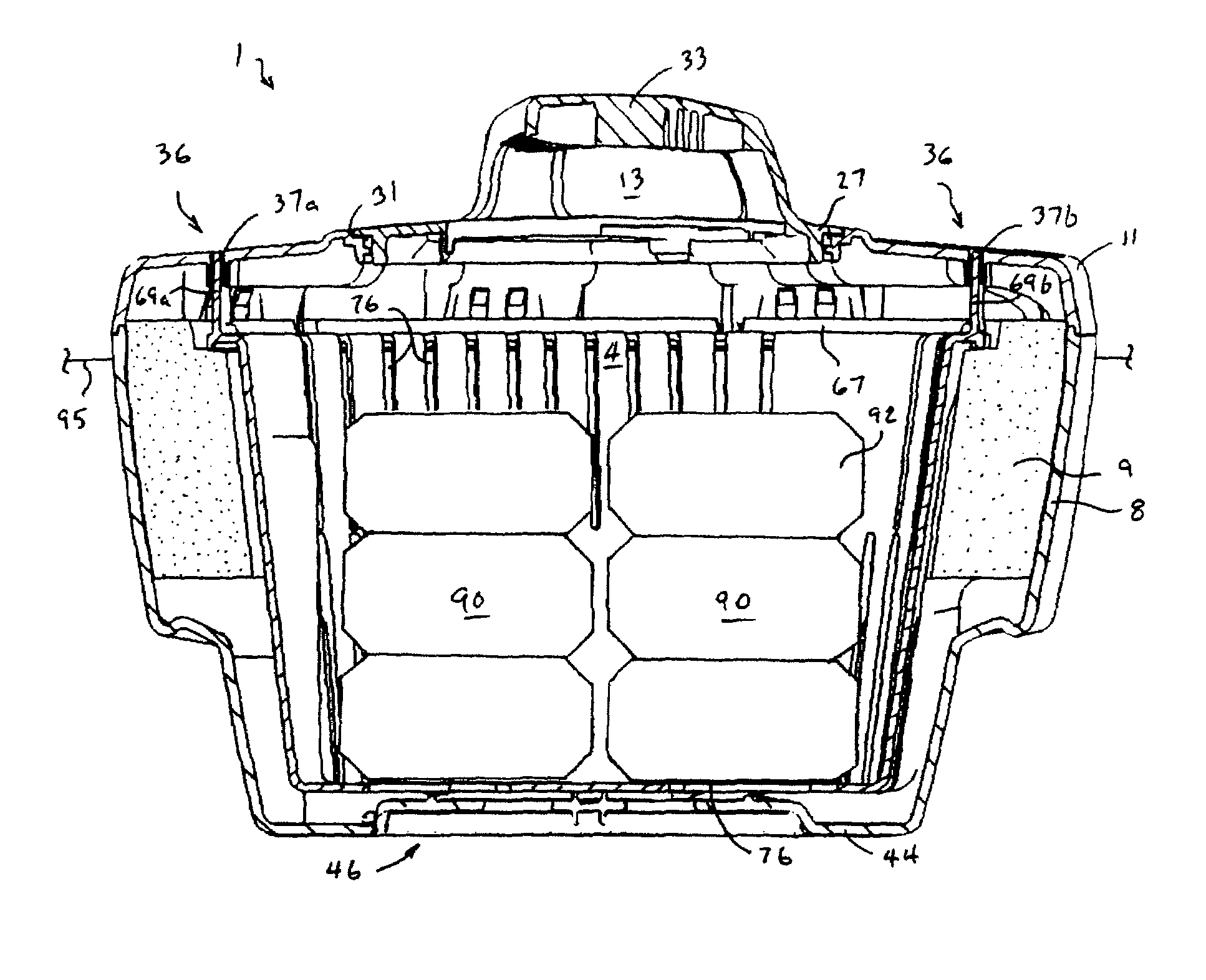
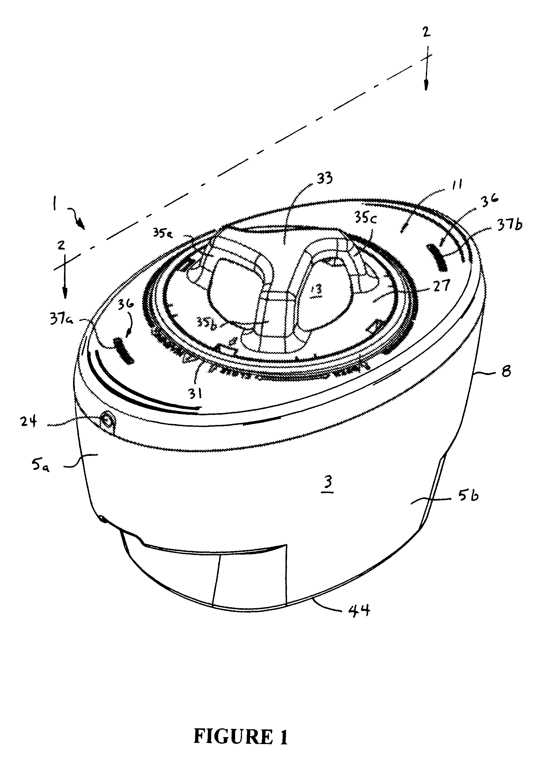
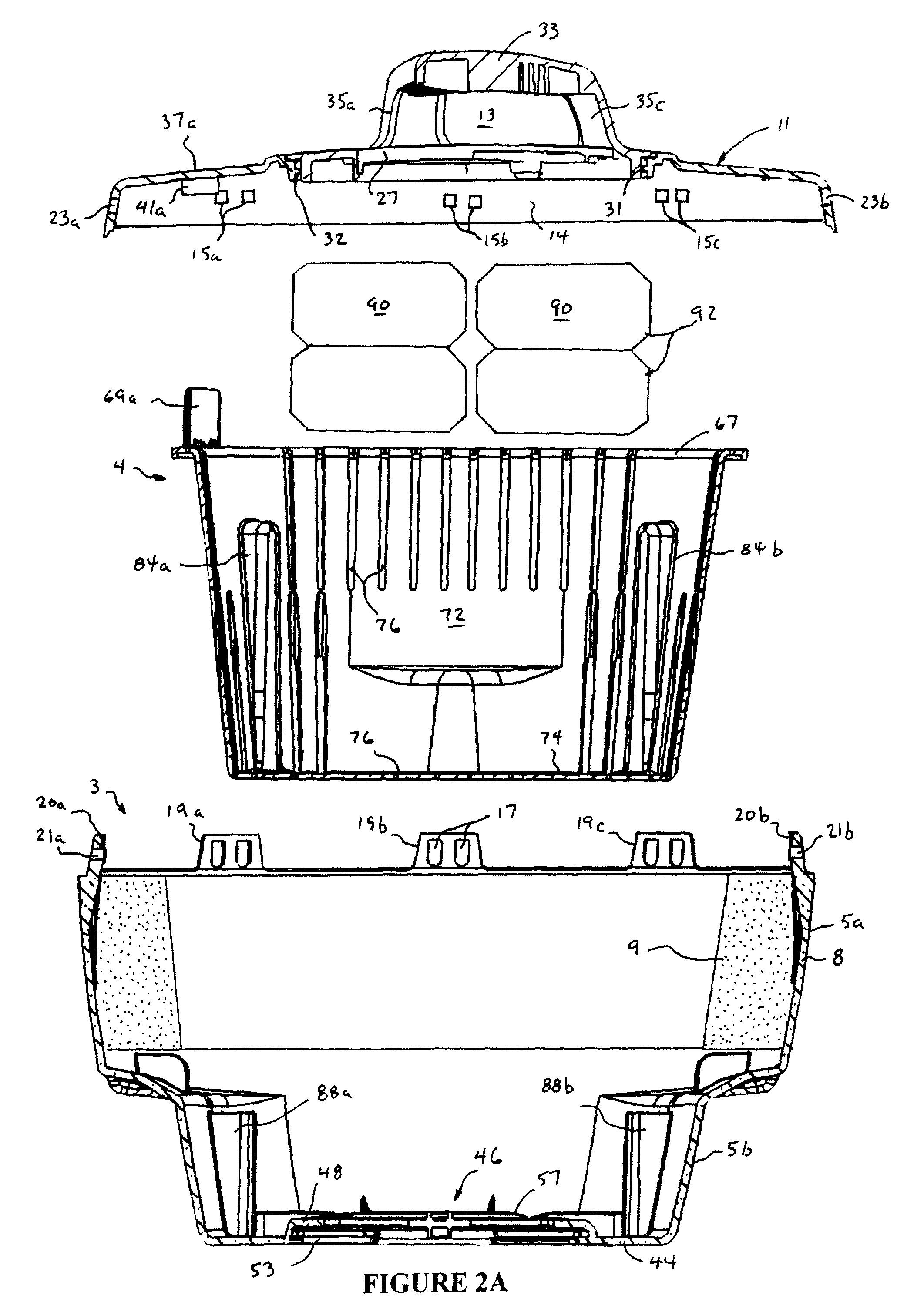
[0020]With reference now to FIGS. 1 and 2A, wherein like numbers designate like components throughout all of the several Figures, the floating dispenser 1 of the invention generally comprises a bucket 3 that contains a basket 4 for holding a solid, dissolvable pool treatment chemical such as tablets of calcium hypochlorite.

[0021]Bucket 3 has a top portion 5a that includes a radially protruding wall 8. Wall 8 contains an elliptical ring 9 of a buoyant, water and chemical resistant polymeric foam, such as closed cell expanded polystyrene that functions as a floatation component when the dispenser is immersed in water. The bucket 3 further has a top wall 11 mounted over its top end 5a that includes a detachably removable lid 13. The buoyancy and positioning of the ring 9 relative to the top wall 11 are selected so that when the dispenser 1 is placed in a pool or other body of water in a fully loaded condition, the dispenser 1 will float in an upright orientation with only the top wall ...


PUM

PropertyMeasurementUnit
movementaaaaaaaaaa
sizeaaaaaaaaaa
sizesaaaaaaaaaa

Abstract

A floating dispenser is provided for dispensing a solid, dissolvable water treatment chemical into ambient water. The dispenser includes a bucket having top and bottom ends, a top wall covering the top end, an opening for admitting ambient water into the bucket interior, and a floatation ring that keeps only the top end above water such that the interior is water filled when the dispenser floats. A basket is disposed in the interior of the bucket for carrying a solid, dissolvable water treatment chemical, such as calcium hypochlorite. The basket is buoyant and movable vertically toward the top wall of the bucket. The dispenser includes a refill indicator that indicates when most of a full load of said chemical has dissolved. The refill indicator includes a pair of tabs that are connected to the basket and slidably mounted in slots in the top wall. The tabs extend above the top wall when the buoyant basket floats upwardly, providing a visual indication of the need for a refill that can easily be seen from a side angle.

Description

FIELD OF THE INVENTION[0001]This invention generally relates to chemical dispensers, and is specifically concerned with a floating dispenser for dispensing a solid, dissolvable water treatment chemical into ambient water, such as a swimming pool.BACKGROUND OF THE INVENTION[0002]Devices for dispensing water treatment chemicals into swimming pools are known in the prior art. Many of these devices include a cylindrical housing for containing a single stack of dissolvable tablets of, for example, calcium hypochlorite. The upper end of the housing is circumscribed by a buoyant material so that the device floats in an upright orientation with its upper end above the water line when placed in a pool. One or more openings are provided at the lower end of the housing to allow ambient water to enter the housing, dissolve the tablets, and provide a stream of halogen solution that disinfects and otherwise treats the ambient water.[0003]In operation, the size, number or path length of water-admi...

Claims


Application Information

Patent Timeline
Patent Type & Authority Patents(United States)
IPC IPC(8): B01D17/12
CPCB01F1/0027C02F1/008C02F1/688C02F2103/42Y10T137/4891B01F21/22
Inventor REED, CHRISTOPHERRAWAT, NIDHIHICKMAN, MELISSASMITH, JEFFREY N.FOSTER, JERRYGABRIEL, MATTHEWHARDING, GREGSTROTHERS, IV, H. SHAWGUYTON, ALLISONMCNEELY, NOAH
Owner BIO LAB
Why Eureka
Try Eureka