Method and system for testing P2 stiffness of a magnetoresistance transducer at the wafer level

Inactive Publication Date: 2011-08-30
WESTERN DIGITAL TECH INC
View PDF39 Cites 157 Cited by
  • Summary
  • Abstract
  • Description
  • Claims
  • Application Information

AI Technical Summary

Benefits of technology

[0006]Various embodiments of the present invention solve the foregoing problem by providing methods and systems for non-destructively testing the stiffness of a P2 layer in a TMR head at the wafer level. By measuring a change in resistance through a TMR film stack as a magnetic field normal to the P2

Problems solved by technology

As the areal density of hard disk drives continues to increase, the design challenges relating to the tunneling magneto-resistive (TMR) film stacks used to manufacture read heads become more acute.
One such challenge relates to the stability of the pinned layer (P2) in a TMR transducer.
In this regard, low pinning strength can lead to early drive reliability failure.
Poor coupling can also deteriorate head performanc

Method used


Image

  • Method and system for testing P2 stiffness of a magnetoresistance transducer at the wafer level
  • Method and system for testing P2 stiffness of a magnetoresistance transducer at the wafer level
  • Method and system for testing P2 stiffness of a magnetoresistance transducer at the wafer level

Examples


Embodiment Construction

[0017]In the following detailed description, numerous specific details are set forth to provide a full understanding of the present invention. It will be apparent, however, to one ordinarily skilled in the art that the present invention may be practiced without some of these specific details. In other instances, well-known structures and techniques have not been shown in detail to avoid unnecessarily obscuring the present invention.

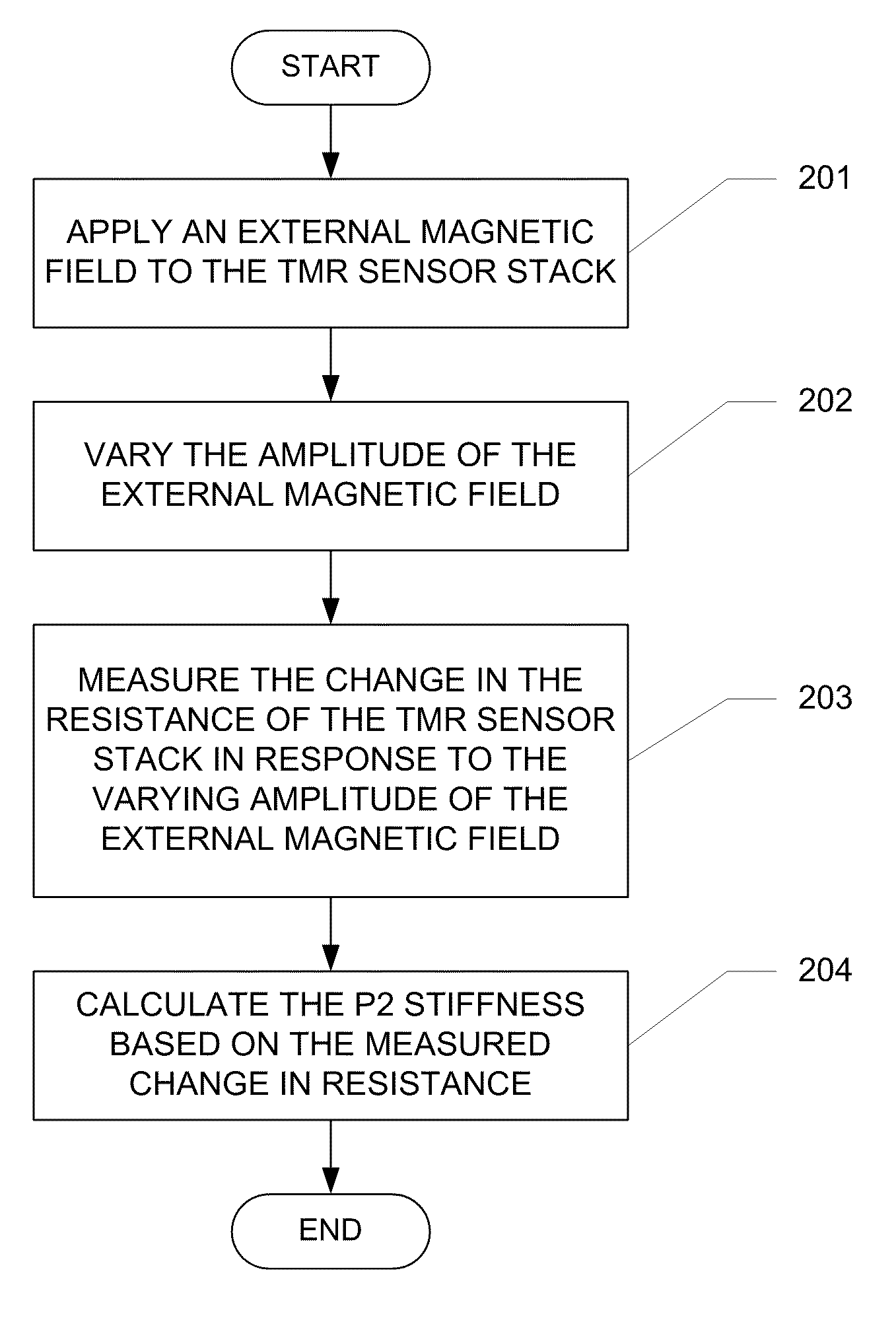
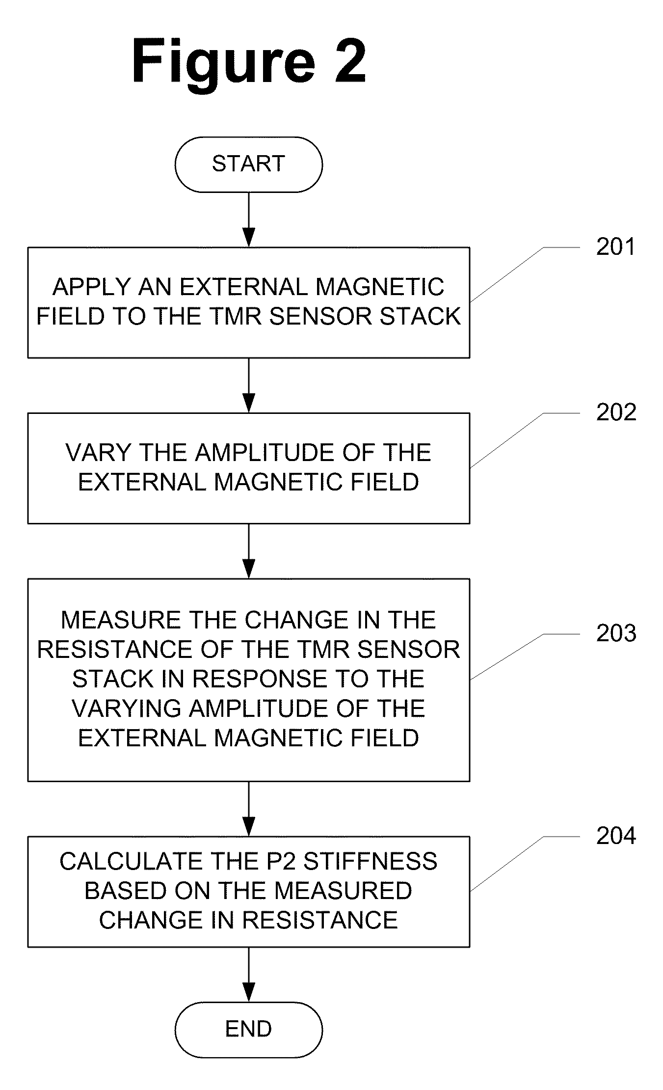
[0018]FIG. 2 is a flow chart illustrating a method of testing the P2 stiffness of a tunneling magnetoresistance (TMR) sensor stack including a P2 pinned layer, in accordance with one aspect of the subject disclosure. The method begins with step 201, in which an external magnetic field is applied to the TMR sensor stack. The external magnetic field is oriented substantially perpendicular to the magnetic field of the P2 pinned layer. According to one aspect of the subject disclosure, the applied magnetic field may be in the same axis as the field of the har...


PUM


Abstract

A method of testing P2 stiffness of a magnetoresistance (MR) sensor stack including a P2 pinned layer is provided. The method comprises the step of applying an external magnetic field to the MR sensor stack. The external magnetic field is oriented substantially perpendicular to a magnetic field of the P2 pinned layer. The method further comprises varying an amplitude of the external magnetic field, measuring a change in a resistance of the MR sensor stack in response to the varying amplitude of the external magnetic field, and calculating the P2 stiffness based on the measured change in resistance.

Description

FIELD OF THE INVENTION[0001]The present invention generally relates to hard disk drives and, in particular, to a method and system for testing P2 stiffness of a magnetoresistance transducer at the wafer level.BACKGROUND OF THE INVENTION[0002]As the areal density of hard disk drives continues to increase, the design challenges relating to the tunneling magneto-resistive (TMR) film stacks used to manufacture read heads become more acute. One such challenge relates to the stability of the pinned layer (P2) in a TMR transducer.[0003]FIG. 1 illustrates a TMR head film stack 100. The TMR head film stack 100 includes two NiFe outer shield layers S1 and S2. Over a seed layer (SL) of Ta or the like is disposed an antiferromagnetic material (AFM), such as IrMn or PtMn. Over antiferromagnetic material AFM is disposed a synthetic antiferromagnet made up of a ferromagnetic material (e.g., CoFeB) pinning layer P1, a spacer layer of Ru, and a ferromagnetic material (e.g., CoFeB) pinned layer P2. A...

Claims


Application Information

Patent Timeline
IPC IPC(8): G01R33/12
CPCG01R33/098
Inventor SHANG, CHANGHE
Owner WESTERN DIGITAL TECH INC
Why Eureka
Try Eureka