Printed circuit board filter having rows of vias defining a quasi cavity that is below a cutoff frequency

a filter and printed circuit board technology, applied in the field of filters, can solve the problems of lossy lossy filter and physical largeness

Active Publication Date: 2011-08-30
HARRIS CORP
View PDF7 Cites 8 Cited by
  • Summary
  • Abstract
  • Description
  • Claims
  • Application Information

AI Technical Summary

Benefits of technology

[0003]The distribution of RF signals in many modern microwave systems is through printed circuit boards because of their low design cost and low production cost. Filter elements are often integrated inside the circuit boards. Some of the filter elements used are parallel coupled filters, shunt stub filters, and coupled resonator filters. However, using these elements to design a high performance low frequency band reject filter often results result in a filter that is physically large and is lossy.
[0004]Methods and systems in accordance with the present invention provide a better low-reject filter for on printed circuit boards that is relatively compact, low loss, and that rejects all frequencies below a certain cutoff frequency.SUMMARY

Problems solved by technology

However, using these elements to design a high performance low frequency band reject filter often results result in a filter that is physically large and is lossy.

Method used


Image

  • Printed circuit board filter having rows of vias defining a quasi cavity that is below a cutoff frequency
  • Printed circuit board filter having rows of vias defining a quasi cavity that is below a cutoff frequency
  • Printed circuit board filter having rows of vias defining a quasi cavity that is below a cutoff frequency

Examples


Embodiment Construction

[0012]Glossary. As used in this description and in the claims, the following terms shall be construed to have the following meanings:

[0013](1) RF frequency bands are referred by their standard nomenclatures, as follows:[0014](a) “L-band” means 1-2 GHz;[0015](b) “S-band” means 2-4 GHz;[0016](e) “Ku-band” means 12-18 GHz;

[0017](2) “antenna” means a structure for radiating or receiving electromagnetic waves;

[0018](3) “low frequency” means frequencies below the operating frequencies of the antenna to be protected;

[0019](4) “cavity” means a metallic enclosure with two openings for RF energies to pass in and out;

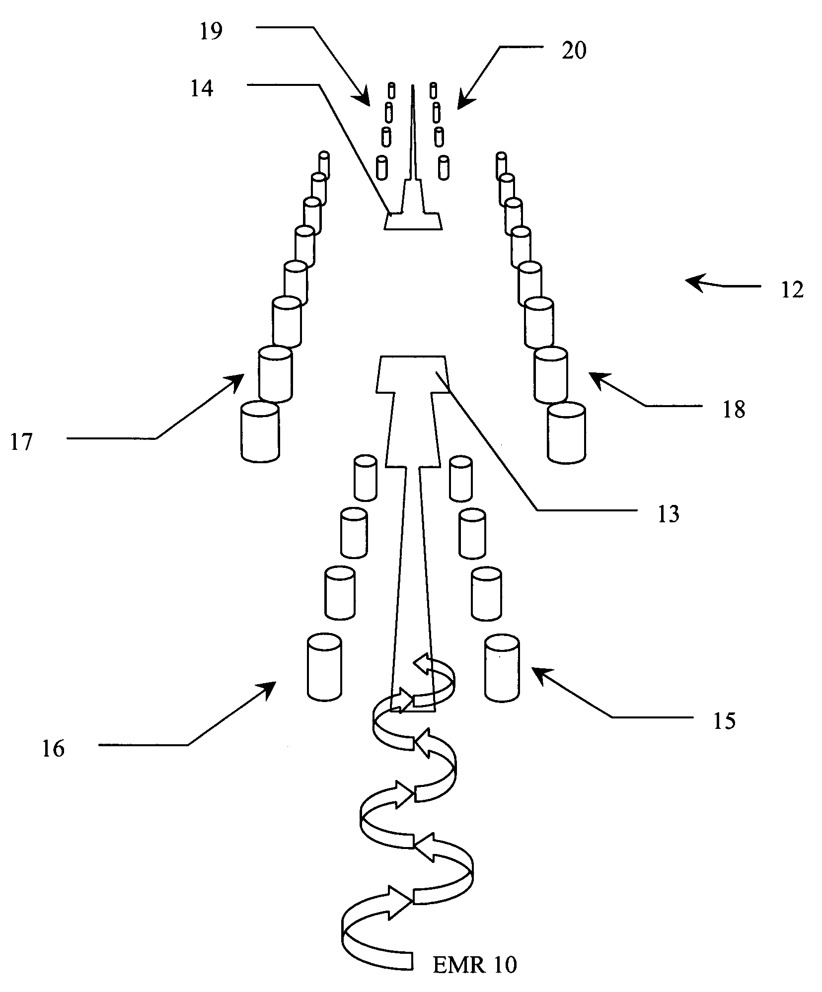
[0020](5) “quasi-cavity” means a structure that acts as a cavity without necessarily requiring a contiguously surrounding wall;

[0021](6) “quasi-waveguide” means structure that acts like a waveguide without necessarily requiring a contiguously surrounding wall;

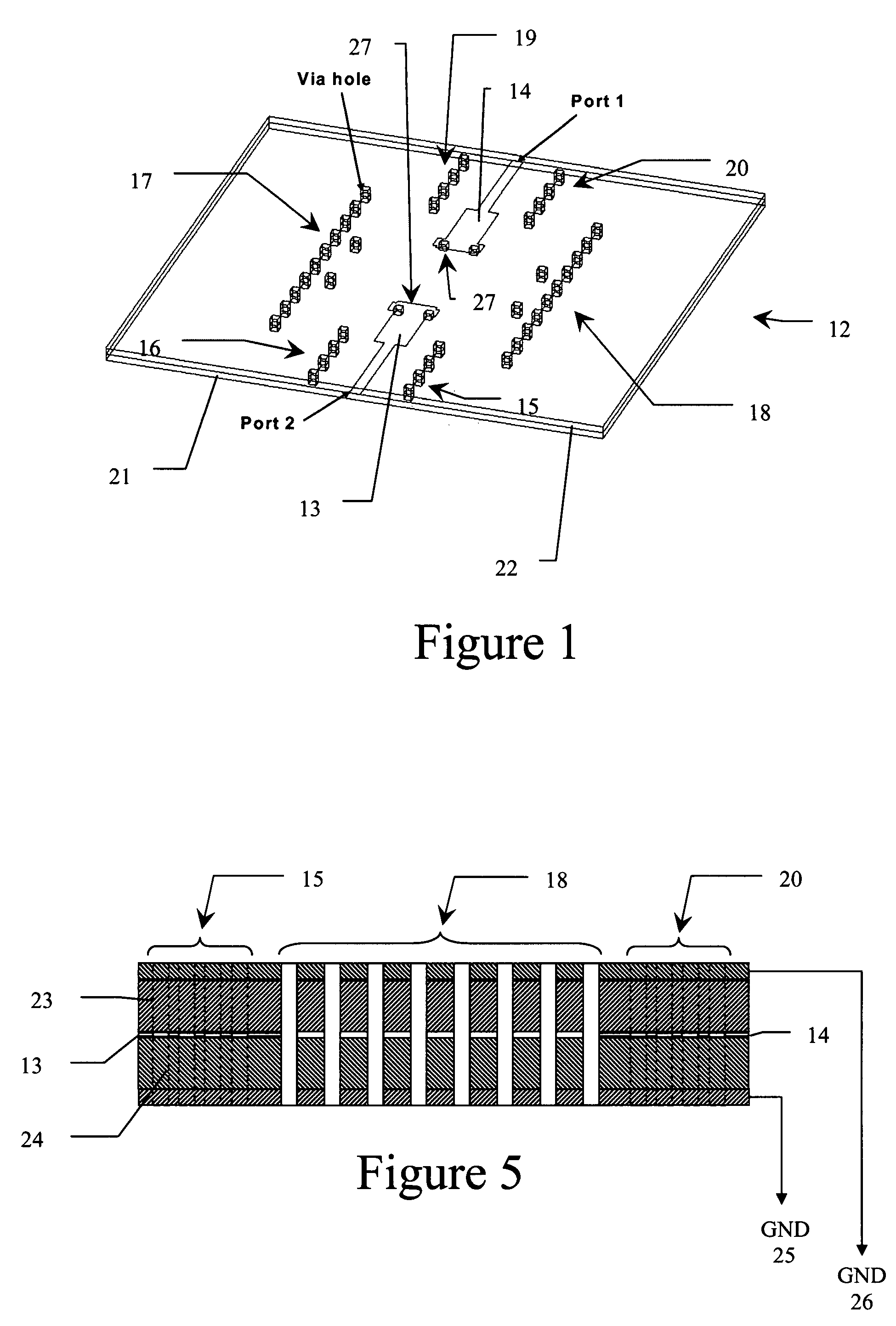
[0022](7) “via-hole” means a hole formed in a printed circuit board and filled with a conductive material; and

[0023](8) “cu...


PUM

PropertyMeasurementUnit
frequencyaaaaaaaaaa
frequencyaaaaaaaaaa
frequencyaaaaaaaaaa

Abstract

A low frequency reject filter element is formed on a printed circuit board that utilizes the fact that power transmission in a waveguide is cut-off below a certain frequency. A quasi waveguide cavity is formed in printed circuit board using the top and bottom ground plane of the stripline circuit and using conductive via holes to form the side walls of the cavity. Waveguide cavity mode is launched from the input and output striplines by shorting them to ground. Transformers and matching via hole elements may be used to improve matching. The resulting filter is compact and is highly effective in suppressing low frequency transmissions.

Description

[0001]This relates to filters in a stripline transmission line medium and in particular to filters on printed circuit boards in antenna arrays.INTRODUCTION[0002]Filters in a microwave system are used to suppress unwanted frequencies that may interfere with the functioning of the microwave system. In particular, an antenna designed to operate in a certain frequency band may be placed in an environment where many other antenna systems operating at different frequencies are transmitting powerful signals. This is often the case in a shipboard platform. Some communication antennae may be operating at Ku band while other long range surveillance radars may be operating at L and S band with very high transmit power. In order for this antenna to operate properly, the signals from the other lower frequency antennae received by this antenna must be substantially suppressed.[0003]The distribution of RF signals in many modern microwave systems is through printed circuit boards because of their l...

Claims


Application Information

Patent Timeline
Patent Type & Authority Patents(United States)
IPC IPC(8): H01P1/207
CPCH01P1/2088H01P5/107H05K1/0239Y10T29/49117H05K2201/0715H05K2201/09618
Inventor CHO, CHING-FAI
Owner HARRIS CORP
Why Eureka
Try Eureka