Respirator fit-testing apparatus and method

a technology of respirator and fit-testing apparatus, which is applied in the field of respirator face mask, can solve the problems of method problems, complicated methods, and the inability to precisely generate and uniformly disperse contaminant particles in air for these tests, so as to minimize the apprehension of test subjects, improve the accuracy of test results, and simplify test procedures

Active Publication Date: 2011-09-06
CRUTCHFIELD CELEVATORON D
View PDF18 Cites 25 Cited by
  • Summary
  • Abstract
  • Description
  • Claims
  • Application Information

AI Technical Summary

Benefits of technology

[0018]The invention relates in general to apparatus and methods for fit testing respirators. More particularly, the invention features improved respirator fit-testing methods and apparatus that includes a single automated, respirator wearer-controlled air-leak measurement unit (i.e., a leak rate analyzer). The invention also relates to respirator fit-testing methods and apparatus that simplify test procedures, improve accuracy of test results, minimize test subject apprehension during testing, and provide a better assessment of respirator integrity for a given individual wearer.
[0023]The pressure transducer senses that the pressure interiorly to the face piece is not the negative pressure value pre-selected and a signal is sent to the electrically controlled air valve interposed between the face piece and the vacuum source. The air valve opens and the vacuum source pulls air through the mass flow meter and the electrically controlled air valve. As the negative pressure interiorly to the face piece approaches the pre-selected level to which the pressure monitor transducer is set, the proportional signal generated by the pressure monitor transducer is reduced, which in turn reduces the size of the orifice in the electrically controlled air valve until the steady-state pre-selected negative pressure has been established in the respirator interior. A period of 3 to 5 seconds is permitted to allow the negative pressure to reach a steady state equilibrium throughout the interior of the face piece, the equipment, and the tubing.
[0024]The ideal situation would be that very little air leaks interiorly to the face piece and thus the electrical voltage output of the pressure monitor transducer would be zero with perhaps a small output from time to time indicating that there was some small amount of leakage, and, as the pressure interiorly to the mask rose, the pressure monitor transducer would detect it. Correspondingly, the electrically controlled air valve would be closed the majority of the time and then opened as it received an electrical signal from the pressure monitor transducer to thereby permit the vacuum pump to regain the negative pressure desired. Thus the system would be indicative of the average of leakage air over an extended period of time.
[0027]The flow rate of air removed from the face piece through the mass flow meter by the vacuum system which was required to maintain the pre-selected negative pressure is equal to the leakage flow rate of air into the respirator. Thus, measurement of the flow rate of the removed air utilizing the mass flow meter gives an absolute determination of leakage around the face piece for the particular negative pressure induced interiorly to the face piece. Obviously, the negative pressure interiorly to the face piece can be increased (made more negative) thereby simulating a wearer working hard and thus demanding more air. Under such varying conditions, the leakage air flow can be determined and the fit factor over the expected simulated conditions determined for one wearer with different respirators. Thus, the best respirator for any particular person may be easily determined.

Problems solved by technology

The techniques by which monodispersed contaminant particles are precisely generated and uniformly dispersed in air for these tests are generally rather complicated.
Another major problem in evaluating respirators through today's methods is how the concentration of the air borne contaminant, more commonly called aerosols, is measured.
However, this method has problems in many cases.
First, the measuring equipment usually lies some distance away from the party under test (usually outside a sealed chamber) and hoses used to convey the breathed air with contaminants may be porous or partially porous to the particular contaminant or may adsorb the contaminant.
Second, as may well be imagined, since wearers' faces are differently shaped and sized, one respirator is not going to fit all people.
In addition, the rate of contaminant leakage changes as the wearer breathes at different rates and volumes due to the strenuousness of the wearer's activity.
Thus, the fit factor determined for a wearer in a resting condition may not adequately describe the fit factor achieved with the same respirator under more vigorous work conditions.
Consequently, missing from the field of respirator fit data is how well respirators fit a person and what degree of protection is afforded a wearer who wears the mask over a long period of time and under varying conditions of work.
While the invention above advanced the state of the art, experience has shown that the improper sequencing of the test steps, or failure of the subject to comply with test requirements, can have adverse effects on test quality and results.
For example, if a test subject prematurely closes the breath inhalation valve of the mask before completing the “preparatory” inhalation that precedes the “holding breath step,” a substantial amount of negative pressure can be trapped inside the respirator, thereby disrupting the remaining test steps.
Such problems have led some evaluators of the prior controlled negative pressure testing method to doubt the veracity and / or general usability of controlled negative pressure fit testing.

Method used


Image

  • Respirator fit-testing apparatus and method
  • Respirator fit-testing apparatus and method
  • Respirator fit-testing apparatus and method

Examples


Embodiment Construction

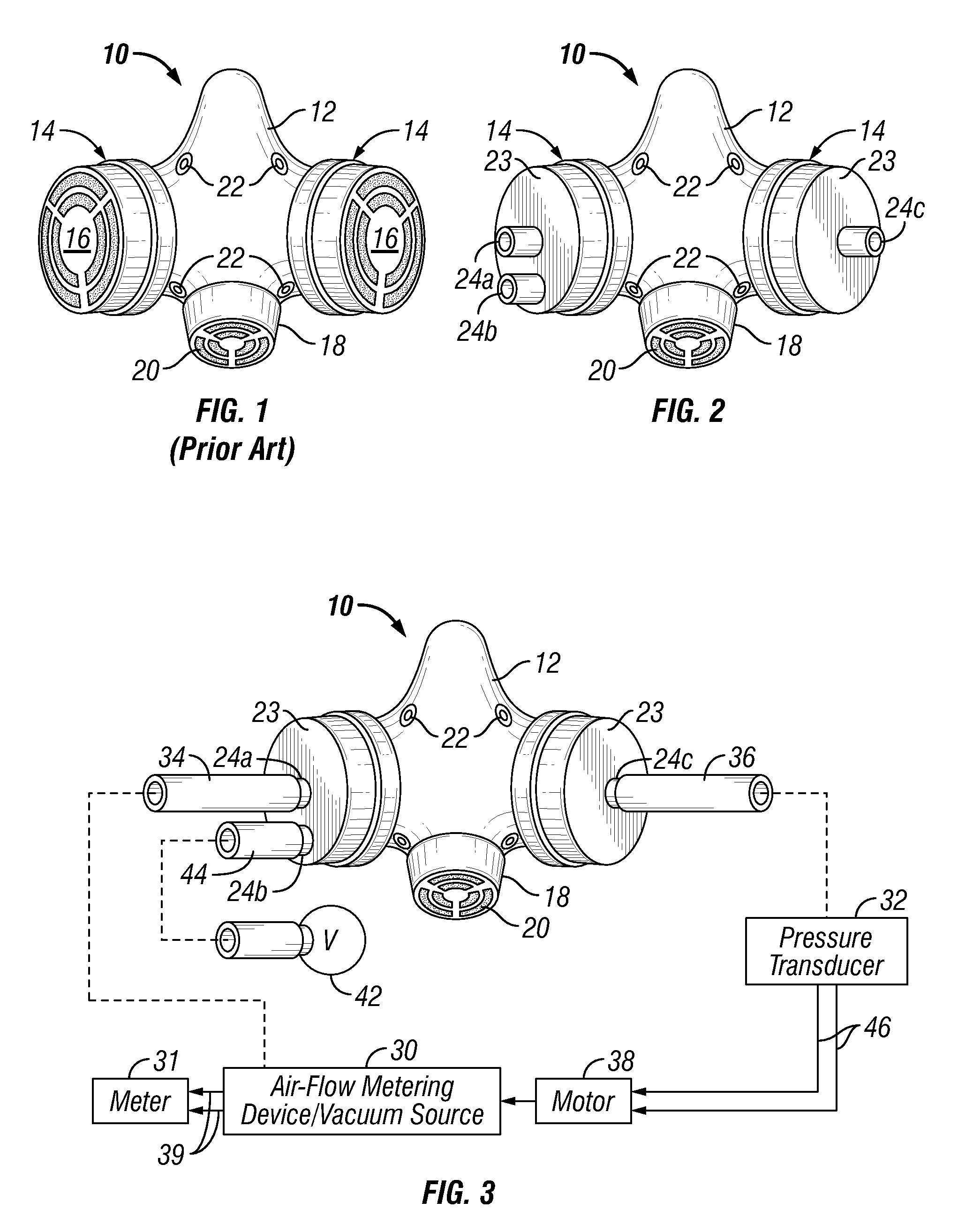
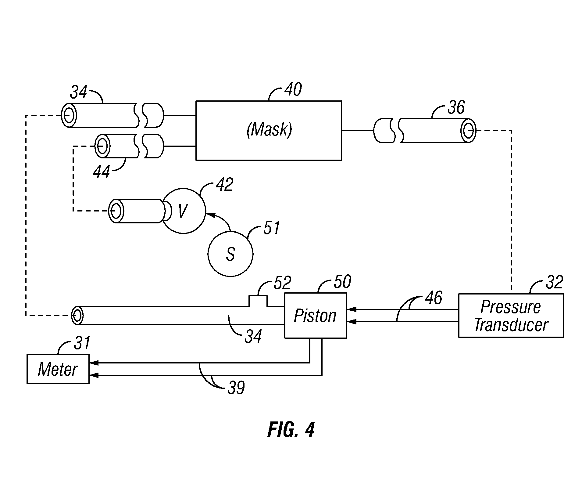
[0035]The invention relates to improved respirator fit-testing methods and apparatus that include a single automated, respirator wearer-controlled air-leak measurement unit. More particularly, the invention relates to respirator fit-testing methods and apparatus that simplifies test procedures, improve accuracy of test results, minimize test subject apprehension during testing, and provide a better assessment of respirator integrity for a given individual wearer.

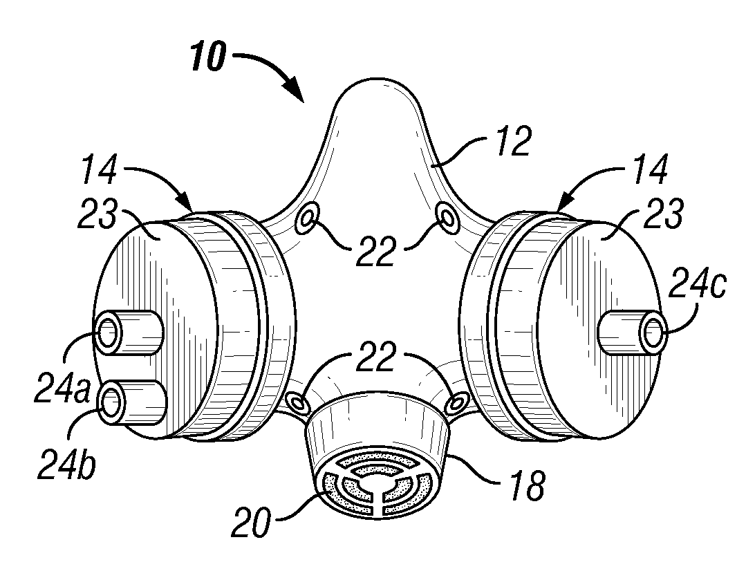
[0036]Referring now to FIG. 1, a front view of a prior art respirator or mask 10 for wearing by a party and which covers the party's nose and mouth is illustrated. Firstly, the face piece 12 is constructed of soft pliable rubber or silicone adapted to insure, as far as possible, an air tight seal between itself and the wearer's face. In many respirators, there is an oversized lip around the edge which resides next to the face to insure the best fit possible. Other respirators or masks not illustrated may be expanded in size ...


PUM


Abstract

Improved respirator fit-test methods and apparatus featuring an automated, respirator wearer-controlled, air-leak measurement system. For fit testing of a respirator positioned on a test subject's face and connected to a controlled negative pressure testing apparatus, the test subject simply holds his breath and then activates a switch in electrical connection with said apparatus, which results in the automatic closure of the breathing port on the respirator and the initiation of a complete fit-testing protocol. The fit-testing apparatus includes a single, self-contained, automated unit that includes a vacuum source (30), an air-flow measuring device, and an air-pressure transducer (32) for connection to a respirator (10) being tested. By measuring the rate of air exhausted from the respirator in order to maintain a constant challenge pressure, an air leakage rate is determined.

Description

BACKGROUND[0001]1. Field of the Invention[0002]The invention relates in general to respiratory face masks and more particularly to methods and apparatus that are especially useful for determining the degree of air-tight fit of a mask worn on the face of a user.[0003]2. Description of the Related Art[0004]Respirators, also known as face masks or gas masks, are used to protect personnel from breathing in contaminants while exposed to a contaminated environment. Respirators fall into two basic classes, the first class being a supplied air respirator in which a flexible hose connects a supply of clean air to the respirator, and the second class where the respirator draws air from a surrounding contaminated environment. The latter class is the most widely used of all respirators and respirators of this class generally are constructed to cover the wearer's nose and mouth with a flexible rubber mask which is held in place with an air tight relationship to the face as much as possible throu...

Claims


Application Information

Patent Timeline
Patent Type & Authority Patents(United States)
IPC IPC(8): A62B18/02A62B18/08G01M3/04A61M15/00A61M16/00A62B27/00
CPCA62B27/00
Inventor CRUTCHFIELD, CLIFTON D.
Owner CRUTCHFIELD CELEVATORON D
Why Eureka
Try Eureka