Programmable ultrasound transmit beamformer integrated circuit and method

a beamformer and integrated circuit technology, applied in oscillator generators, piezoelectric/electrostrictive/magnetostrictive devices, instruments, etc., can solve the problem of dramatic increase in the cost per transmit channel of such pulsers compared to 2-level or 3-level pulsers

Active Publication Date: 2011-09-06
MICROCHIP TECH INC
View PDF8 Cites 25 Cited by
  • Summary
  • Abstract
  • Description
  • Claims
  • Application Information

AI Technical Summary

Problems solved by technology

The cost per transmit channel of such pulsers compared to a 2-level or 3-level pulser increases dramatically.

Method used


Image

  • Programmable ultrasound transmit beamformer integrated circuit and method
  • Programmable ultrasound transmit beamformer integrated circuit and method
  • Programmable ultrasound transmit beamformer integrated circuit and method

Examples


Embodiment Construction

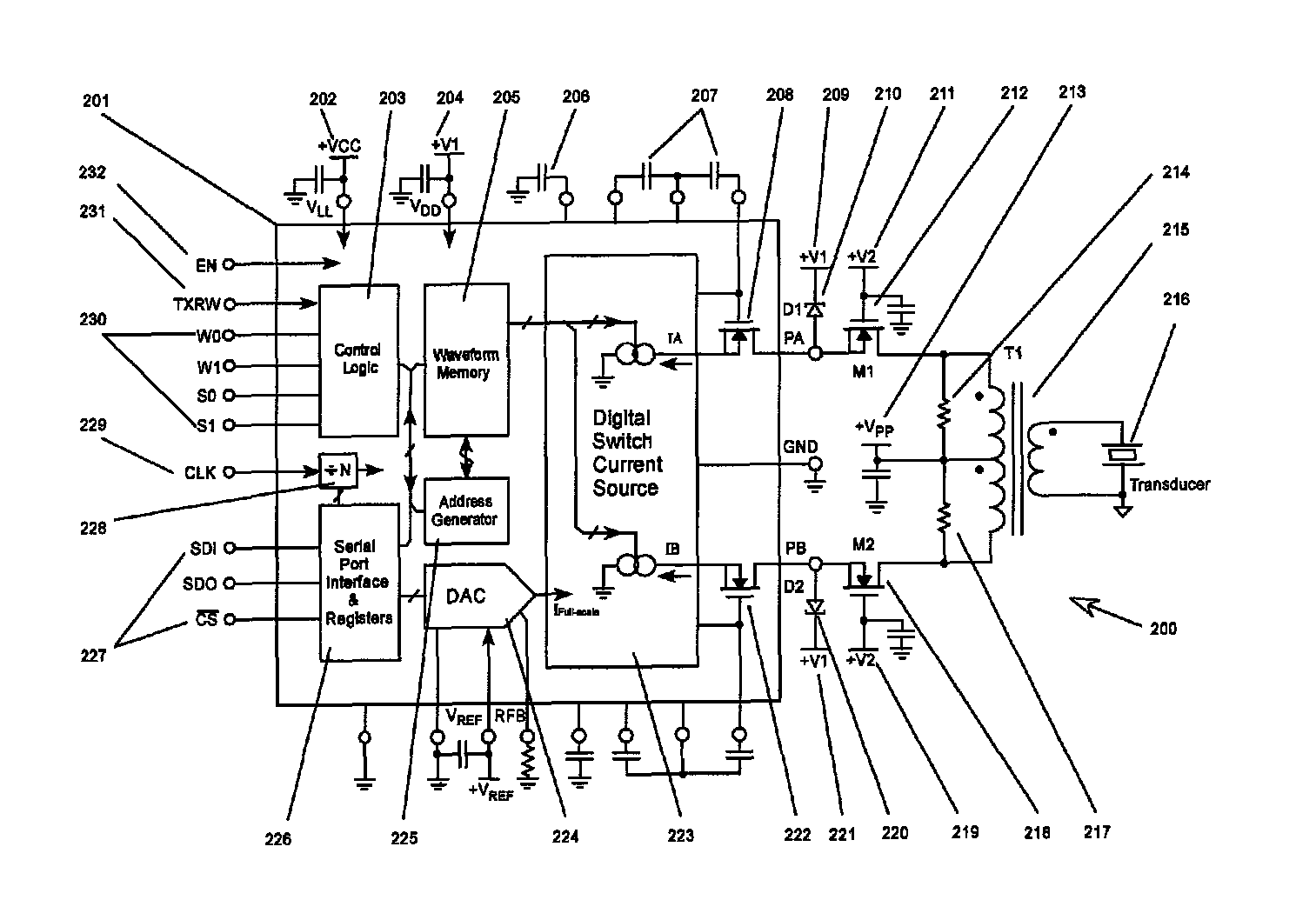
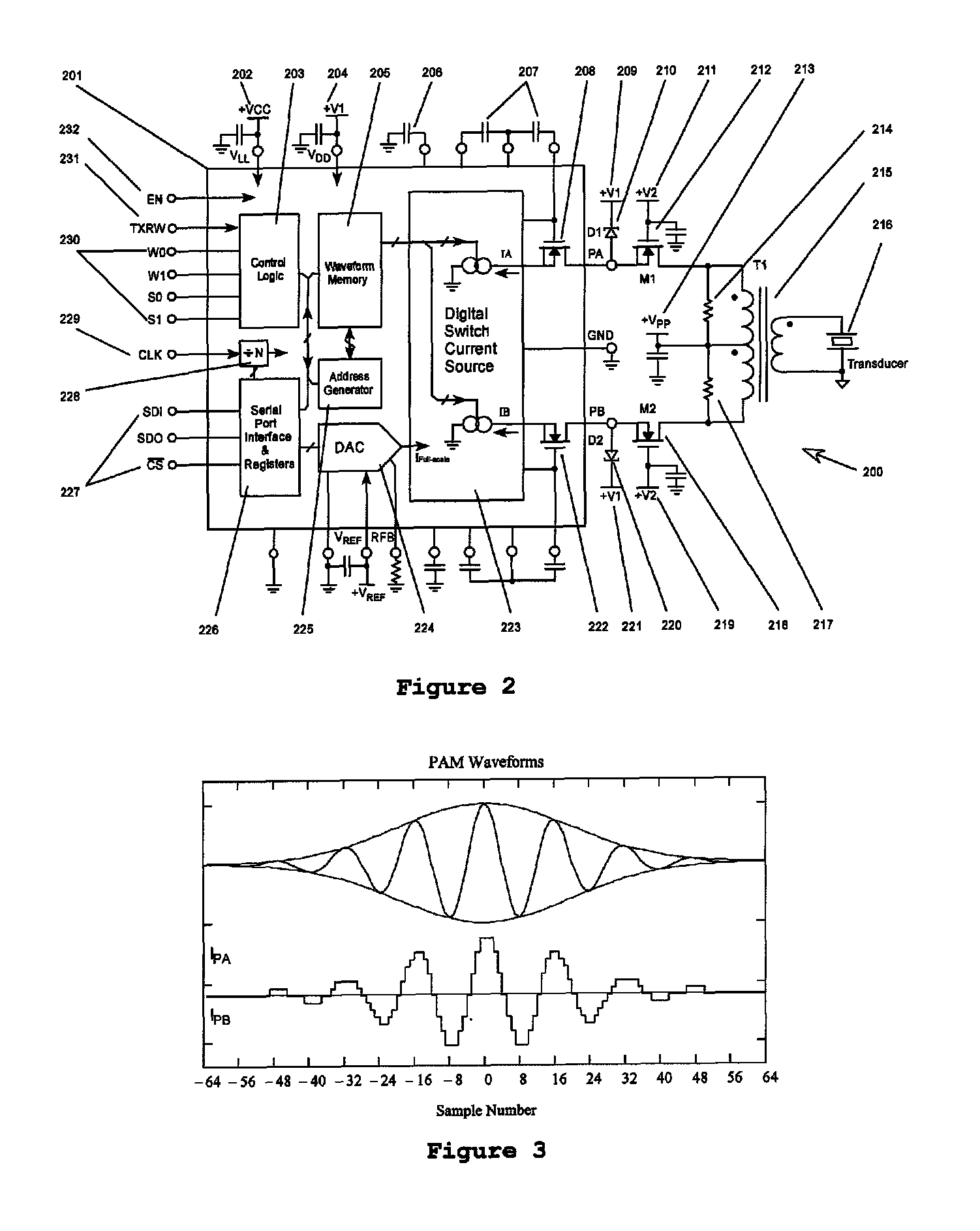
[0012]In various embodiments, the waveform generators of the present invention provide ultrasound imaging probe transducer excitation using a large number array of high voltage and high current transmit pulse waveform generators that may be controlled by a digital logic interface directly with fast response and precise timing. Electronics controlled dynamic focus, acoustic phase-array, and transmitting beamforming technology may be used in color Doppler image portable ultrasound machines. In various embodiments, the waveform generators of the present invention provide digital controlled, programmable high voltage waveform multiple generator channels that are integrated into very small ICs. In various embodiments, the waveform generators of the present invention may generate various transmitting waveforms, and include only two high current output stage MOSFETs.

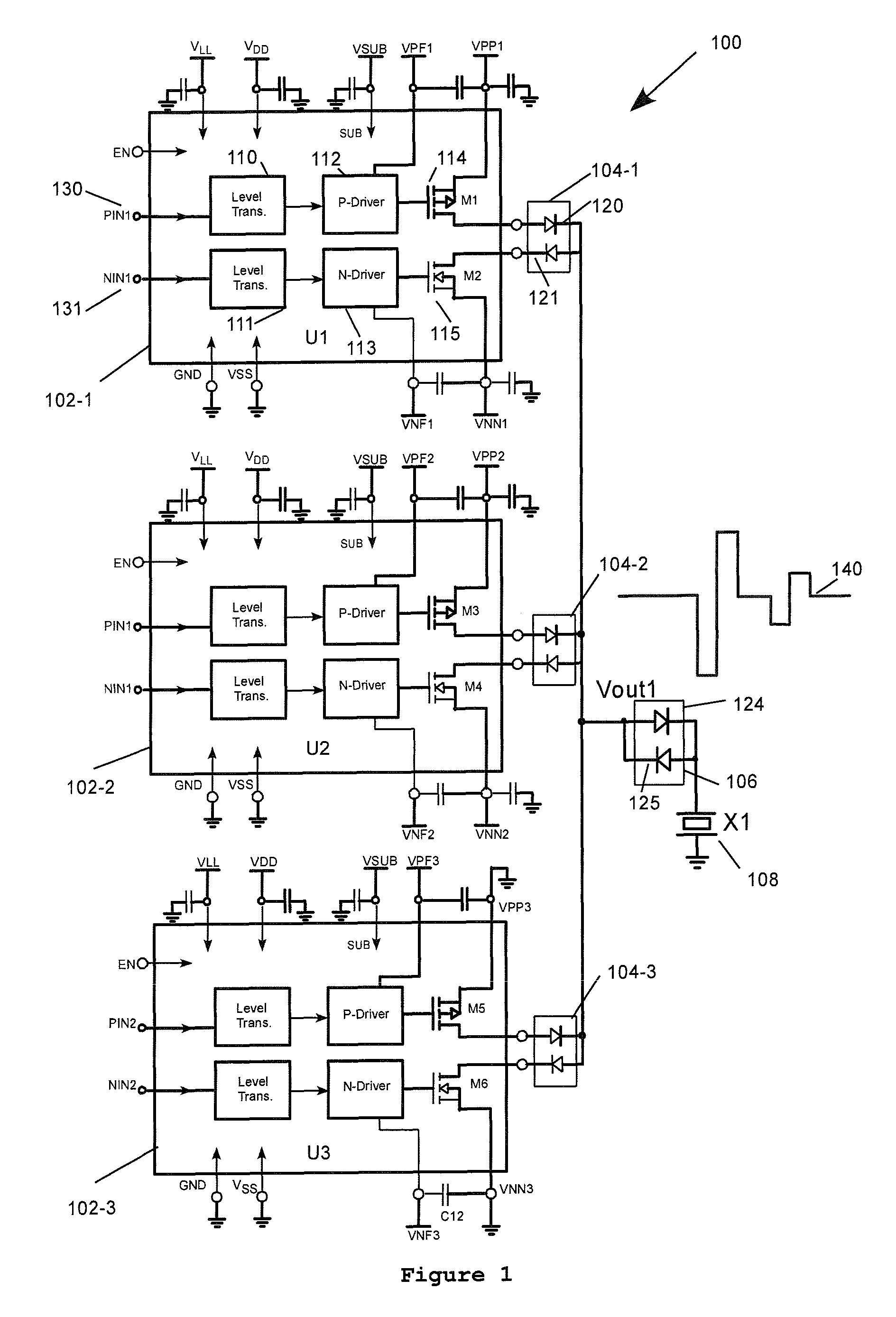
[0013]Referring to FIG. 1, a schematic diagram illustrating a conventional 5-level high voltage pulser 100 with a return-to-z...


PUM


Abstract

An electrical waveform generating circuit has a programmable current source-driver. A digital switched current source is coupled to the programmable current source-driver and controlled by waveforms stored in the programmable current source-driver. A plurality of MOSFETs is coupled to the programmable current source driver. A center-tapped RF transformer is provided and has a primary coupled to the plurality of high voltage MOSFETs. A transducer is coupled to a secondary of the RF transformer.

Description

RELATED APPLICATIONS[0001]The present provisional application is related to U.S. patent application entitled, “Ultrasound Transmit Beamformer Integrated Circuit and Method”, Filed Feb. 15, 2007, and having U.S. Ser. No. 11 / 675,517 in the name of Lazar A. Shifrin. This patent application further claims the benefit of U.S. Provisional Application No. 61 / 073,850, filed Jun. 19, 2008, entitled “PROGRAMMABLE ULTRASOUND TRANSMIT BEAMFORMER INTEGRATED CIRCUIT AND METHOD” in the name of the same inventor, and which is incorporated herein by reference in its entirety.FIELD OF THE INVENTION[0002]This invention relates to a programmable ultrasound transmit beamformer waveform generator, and more particularly, to an ultrasound pulse waveform generator circuit and method with waveform and transmitting sequence control data memory for driving a piezoelectric transducer array probe for transmit beamforming and dynamic focusing.BACKGROUND OF THE INVENTION[0003]Ultrasound array transmitters in medic...

Claims


Application Information

Patent Timeline
Patent Type & Authority Patents(United States)
IPC IPC(8): H03B21/00
CPCG10K11/346
Inventor CHU, CHING
Owner MICROCHIP TECH INC
Why Eureka
Try Eureka