Line imaging systems and methods for laser annealing

a line image and laser annealing technology, applied in the field of line image formation, can solve the problems of inefficient use of high-intensity light from the light source, inability to use a binary optic approach to produce a long, narrow line focus, and inability to achieve uniformity based on kohler principles

Inactive Publication Date: 2011-09-06
ULTRATECH INT INC
View PDF3 Cites 50 Cited by
  • Summary
  • Abstract
  • Description
  • Claims
  • Application Information

AI Technical Summary

Problems solved by technology

However, the coherence length for a CO2 laser is relatively long, typically several meters, making it unfeasible to use a binary optic approach to produce a long, narrow line focus with ˜10% (+/−5%) unifor

Method used


Image

  • Line imaging systems and methods for laser annealing
  • Line imaging systems and methods for laser annealing
  • Line imaging systems and methods for laser annealing

Examples


examples

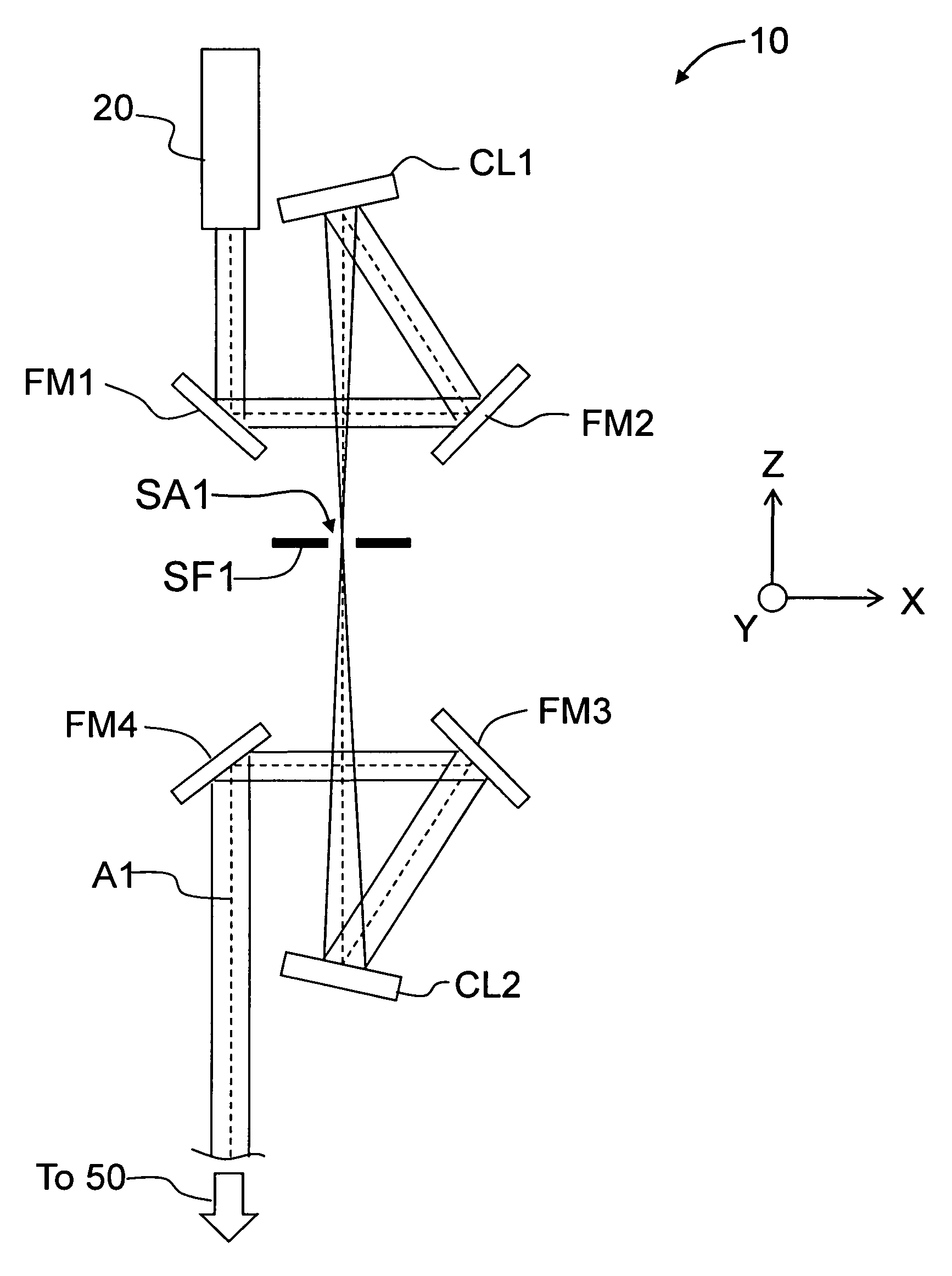
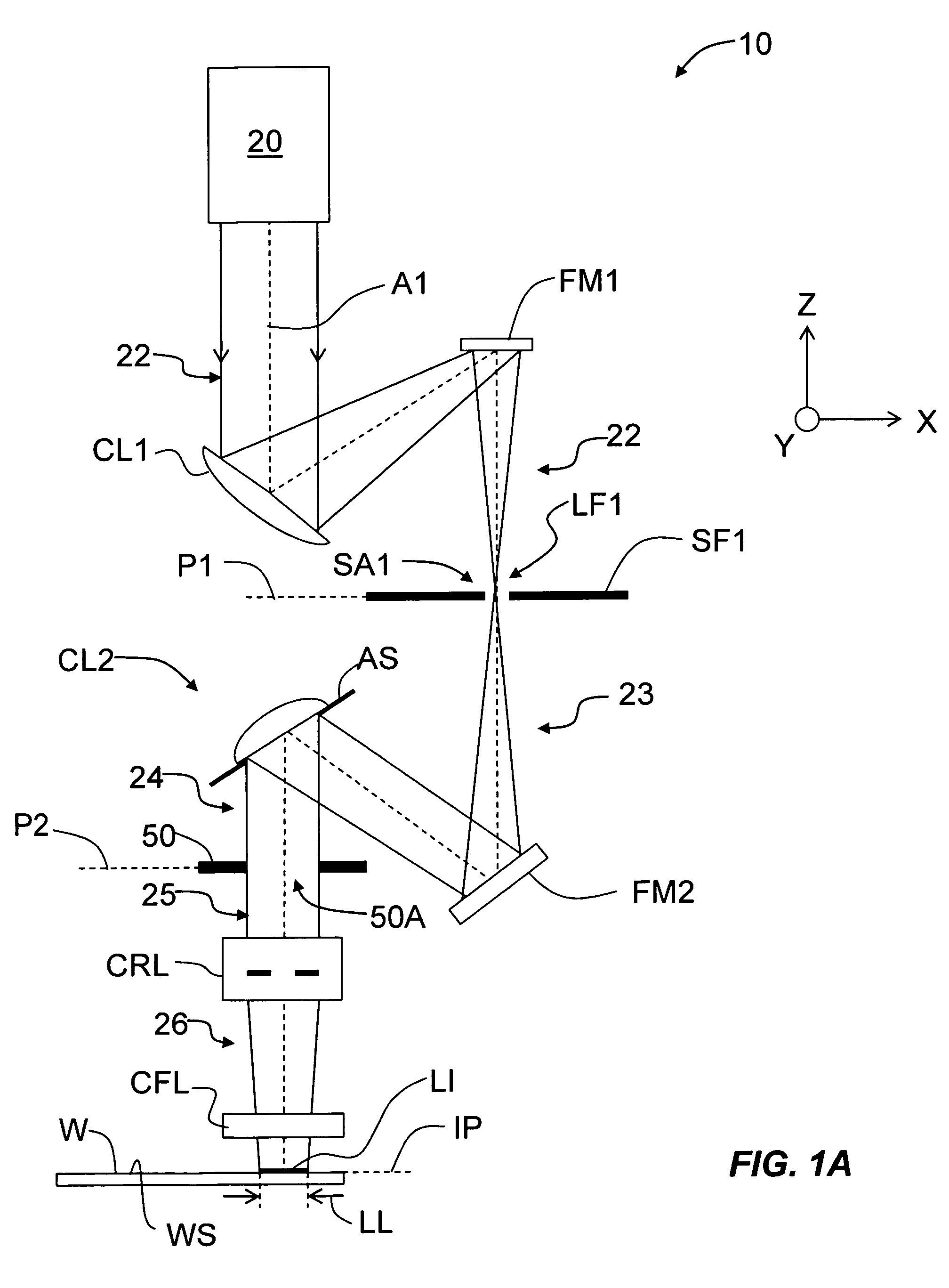
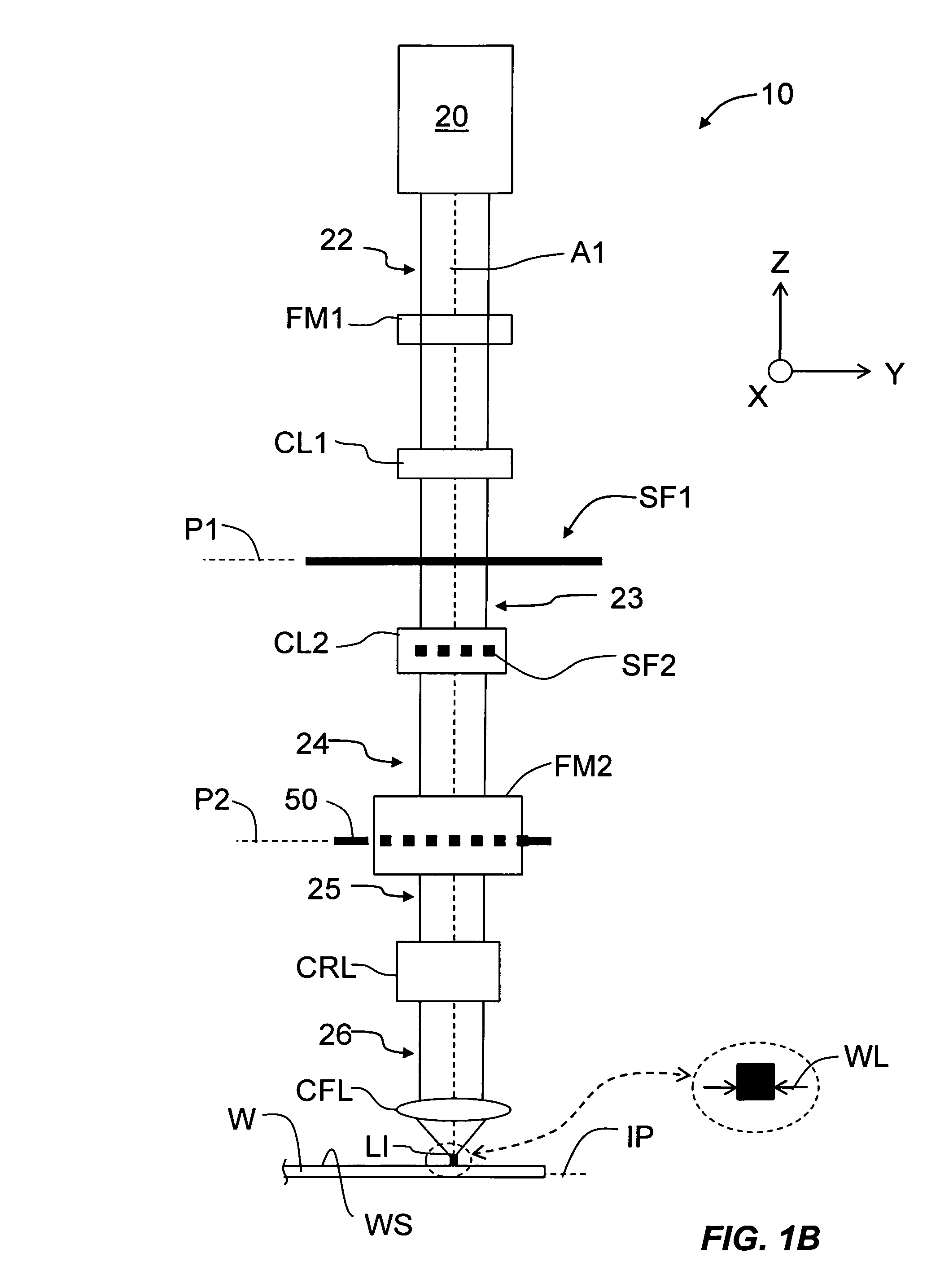
[0040]As discussed above, conventional line-forming optical systems are optimized to produce a Gaussian light beam, which is then truncated to pass a narrow central portion of the light beam, resulting in a substantial loss of light in the final output light beam.

[0041]FIG. 6 plots an example normalized intensity versus position of input light beam 22 at spatial filter SF1 for a conventional line-forming optical system. The spatial filter width W1=WC, which corresponds to forming a substantially Gaussian light beam 23 in the X-direction. In the calculation of the plot of FIG. 6, the spatial filter width W1=WC=2*(λ / D)*F=0.87 mm, where the laser wavelength λ=10.6 microns, the focal length F1 and clear aperture (diameter) D of cylindrical lens system CL1 is F1=900 mm and D=22 mm.

[0042]The length LL of line image LI is 7.47 mm and is defined as a normalized intensity of ≧0.9. The power density of the light beam at the image plane (and thus at wafer surface WS) is 63.3 watts / mm2. Conspic...


PUM

PropertyMeasurementUnit
Lengthaaaaaaaaaa
Lengthaaaaaaaaaa
Widthaaaaaaaaaa

Abstract

The line imaging system includes a laser, first and second cylindrical optical systems with a first spatial filter disposed therebetween, a knife-edge aperture, a cylindrical relay system, and a cylindrical focusing lens. The first spatial filter is configured to truncate a line focus within the central lobe to form a first light beam. The second cylindrical lens system is arranged in the far field and is configured to perform spatial filtering to pass central intensity lobes of the first light beam while blocking outlying intensity lobes. The resultant twice-filtered light beam is has a relatively flat-top intensity distribution associated with the long direction of the line image so that subsequent truncation by the knife-edge aperture transmits more light than conventional line imaging systems. A laser annealing system that employs the line imaging system is also disclosed.

Description

FIELD[0001]The present disclosure relates generally to the formation of line images using light beams, and in particular to systems and methods for improved line imaging for laser annealing applications.BACKGROUND ART[0002]There is a variety of applications that require the use of a uniform line image formed from a coherent light beam. One such application is laser thermal processing (LTP), also referred to in the art as laser spike annealing (LSA) or just “laser annealing,” which is used in semiconductor manufacturing to activate dopants in select regions of a semiconductor wafer when forming active microcircuit devices such as transistors. Laser annealing uses a scanned line image from a light beam to heat the surface of the wafer to a temperature (the “annealing temperature”) for a time long enough to activate the dopants but short enough to minimizing dopant diffusion. The time that the wafer surface is at the annealing temperature is determined by the power density of the line ...

Claims


Application Information

Patent Timeline
IPC IPC(8): H01S3/10
CPCB23K26/0643B23K26/0656B23K26/0853B23K26/0738H01L21/268B23K26/066H01L21/67115
Inventor ANIKITCHEV, SERGUEI
Owner ULTRATECH INT INC
Why Eureka
Try Eureka