Dispersion shifted optical fiber

a technology of optical fiber and shifted optical fiber, applied in the field of shifted optical fiber, can solve the problems of weak confinement effect of propagation mode, increased loss with wavelength increase, and increased optical loss at longer wavelengths, and achieve the effect of low dispersion slop

Inactive Publication Date: 2011-09-06
NIPPON TELEGRAPH & TELEPHONE CORP +1
View PDF16 Cites 2 Cited by
  • Summary
  • Abstract
  • Description
  • Claims
  • Application Information

AI Technical Summary

Benefits of technology

[0014]The configuration makes it possible to implement the dispersion shifted optical fiber that has the zero dispersion and low dispersion slope at the wavelengths of 1.55 μm band by providing the central portion of the core section with the region having the high relative refractive index difference by adding dopant to the central portion, by forming holes in a lattice fashion in the cladding region of the dispersion compensated fiber having large negative dispersion (normal dispersion) in the 1.55 μm band, and by balancing the normal dispersion with the effect of the waveguide dispersion with large anomalous dispersion due to the holes. The dispersion slope of the waveguide dispersion caused by the effect of the holes is preferably positive or zero.

Problems solved by technology

A first drawback is that since the dispersion slope utilizes a negative region (in which the dispersion reduces as the wavelength increases), the confinement effect of the propagation mode is weak, and the loss increases with an increase of the wavelength.
In addition, as for a structure that modifies part of the optical fiber as shown in FIG. 10 by doping GeO2 into the central portion of the core section so that a refractive index at that portion becomes higher than its periphery, it also has a drawback that the optical loss increases at longer wavelengths like the structure as shown in FIG. 10, when the zero dispersion is implemented by the effect of the structure dispersion in the cladding section.
In addition, since the weak optical confinement effect can easily bring about microbending loss, it is difficult to construct a low loss transmission line by a cable using the conventional technique.
Furthermore, since a bending loss can easily occur because of the same reason, it is difficult to place the fiber in a small diameter when using the present optical fiber as an optical component.
A second drawback is that since the conventional dispersion shifted optical fiber has a small core diameter of about 2.4 μm as compared with a commonly used single-mode fiber with the core diameter of about 10 μm, or a commonly used optical fiber with the core diameter of 8-10 μm, the splice loss with these fibers is large of about a few decibels.

Method used


Image

  • Dispersion shifted optical fiber
  • Dispersion shifted optical fiber
  • Dispersion shifted optical fiber

Examples


embodiment 1

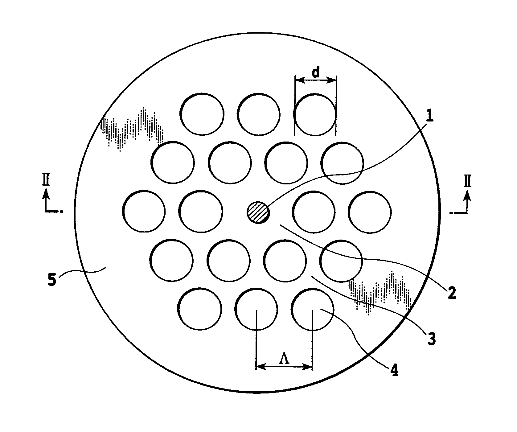
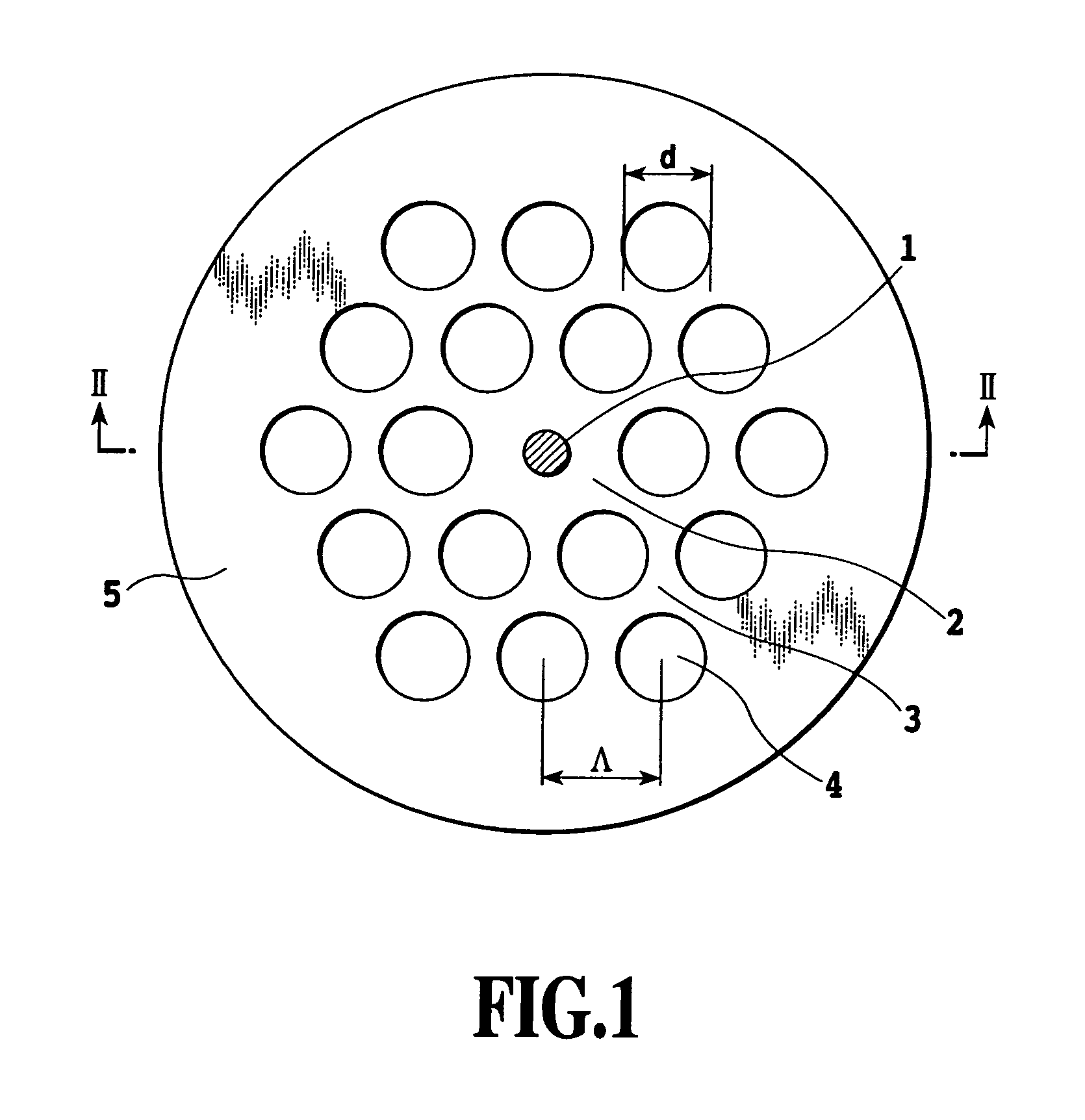
[0029]FIG. 1 is a cross-sectional view showing a structure of an embodiment 1 of the dispersion shifted optical fiber in accordance with the present invention.

[0030]In FIG. 1, the reference numeral 1 designates a heavily GeO2 doped core region “a”; 2 designates a core region “b” composed of pure SiO2 glass; 3 designates a cladding section surrounding the core region; and 5 designates a jacket section. The cladding section 3 has a lot of apertures 4 (called holes 4 from now on) extending in the longitudinal direction of the optical fiber.

[0031]The holes 4 in the cladding section 3 are not located at random, but have a honeycomb structure composed of regular hexagons which have a side length of Λ, and serve as a primitive lattice. Here, the diameter of the holes 4 is represented by d.

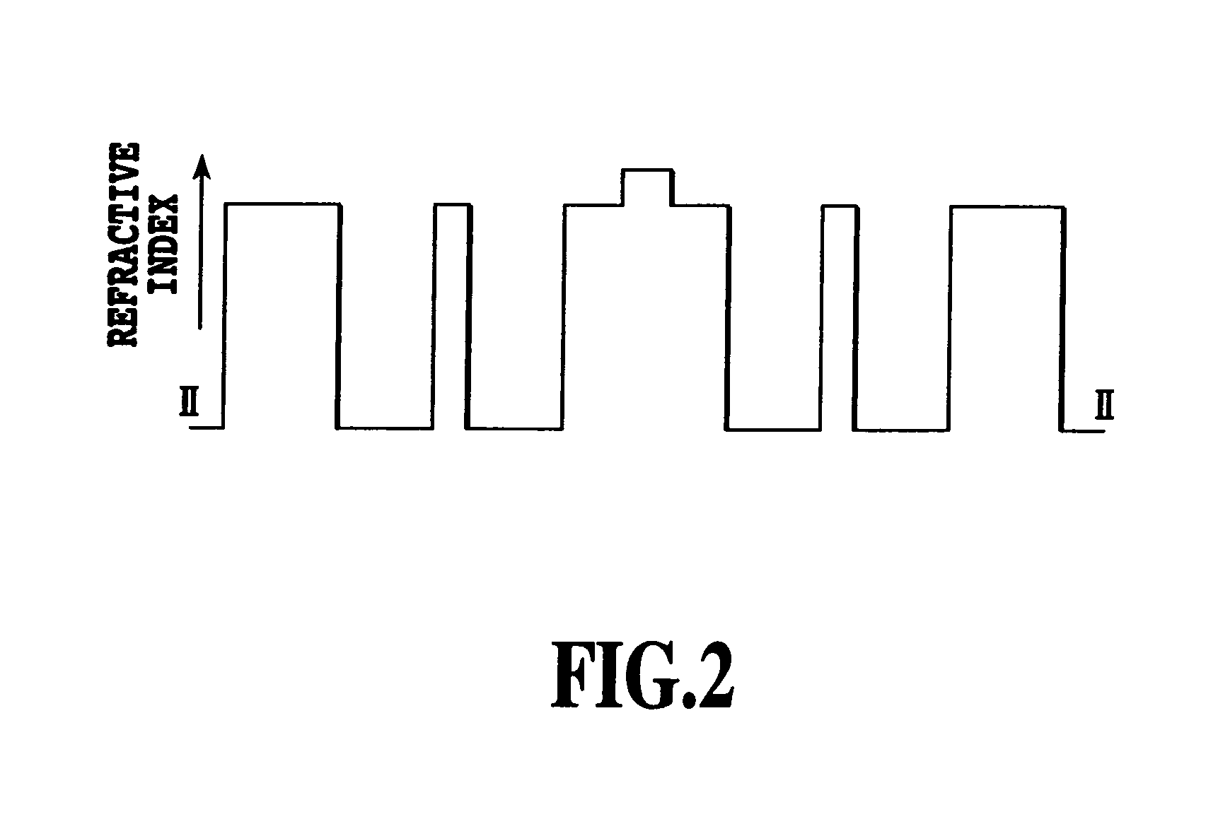
[0032]FIG. 2 is a diagram showing the refractive index distribution of the cross-section along a line II-II of FIG. 1. The lowest level represents the refractive index of the holes (n=1). The core region ...

embodiment 2

[0039]In the present embodiment 2 in accordance with the present invention, the refractive index distribution of the core section “a”, which is the stepwise refractive index distribution in the embodiment 1, is made double cladding type or triple cladding type. FIGS. 4A and 4B show examples of the refractive index distribution: FIG. 4A shows double cladding type refractive index distribution; and FIG. 4B shows triple cladding type refractive index distribution. Except for the holes 4, the refractive index distribution of FIGS. 4A and 4B is equivalent to the refractive index distribution of a well-known dispersion compensated fiber. The refractive index distribution can implement an optical fiber with large normal dispersion.

[0040]Surrounding the core regions 1 and 2, which have the foregoing refractive index distribution, with the highly regularly arranged holes 4 can compensate for the normal dispersion caused by the contribution of the core region by the anomalous dispersion due t...

embodiment 3

[0045]FIG. 6 is a view showing the embodiment 3 in accordance with the present invention. In FIG. 6, the reference numeral 11 designates a core region “a” that is heavily doped with GeO2; 12 designates a core region “b” composed of pure SiO2; 13 designates a cladding section; 14a designates a hole “a”; 14b designates a hole “b”; and 15 designates a jacket section.

[0046]The holes “b” are placed in such a manner that they are adjacent to the core region, and has two-fold axial symmetry. The diameter of the holes b is made greater or less than that of the holes “a”.

[0047]FIG. 7 is a diagram showing the refractive index distribution of the cross-section along a line VII-VII of FIG. 6. That the holes “a” and “b” have different diameters brings about anisotropy in the equivalent refractive indices in the x and y axis directions of FIG. 7. As a result, the propagation mode polarized at the x and y directions, has large birefringence. The large birefringence reduces the polarization crossta...


PUM


Abstract

A 1.55 μm band dispersion shifted optical fiber is provided which has a low loss and low dispersion slope. A core region “a” is heavily doped with GeO2 . A core region “b” is composed of pure SiO2 glass. A cladding section is arranged around the core region. The cladding section has a lot of holes extending in the longitudinal direction of the optical fiber. The holes of the cladding section are not located at random, but have a honeycomb structure composed of regular hexagons which have a side length of Λ, and serve as a primitive lattice. The center of the core section has a region having a refractive index higher than that of the periphery of the core section. The core section has the refractive index distribution in which the group velocity dispersion at the operation wavelength of the region becomes the normal dispersion.

Description

TECHNICAL FIELD[0001]The present invention relates to a dispersion shifted optical fiber, and more particularly to a dispersion shifted optical fiber utilized for optical communication networks and optical signal processing.BACKGROUND ART[0002]FIG. 10 is a cross-sectional view showing a structure of a conventional dispersion shifted photonic crystal fiber. In FIG. 10, the reference numeral 21 designates a core section, 23 designates a cladding section, 24 designates a hole and 25 designates a jacket section. The holes 24 in the cladding section 23 are not located at random, but have a honeycomb structure composed of regular hexagons which have a side length of Λ, and serve as a primitive lattice. Here, the diameter of the holes 24 is represented by d.[0003]The optical fiber has an effective refractive index lower than the refractive index of the core section 21 because of the holes 24 in the cladding section 23 so that the mode guided through the core section 21 is confined and tran...

Claims


Application Information

Patent Timeline
Patent Type & Authority Patents(United States)
IPC IPC(8): G02B6/028G02B6/02G02B6/032
CPCG02B6/02042G02B6/02242G02B6/02276G02B6/02338G02B6/03627G02B6/03644G02B6/03688G02B6/02347G02B6/02361G02B6/0281
Inventor SUZUKI, KAZUNORIKAWANISHI, SATOKIKUBOTA, HIROKAZUTANAKA, MASATOSHIFUJITA, MORIYUKI
Owner NIPPON TELEGRAPH & TELEPHONE CORP
Why Eureka
Try Eureka