Supercharge Your Innovation With Domain-Expert AI Agents!

Method and apparatus for optimizing output power levels in power amplifiers

a power amplifier and output power technology, applied in the field of power amplifiers, can solve the problems of signal failing the prescribed modulation mask, signal to fail the amplitude distortion of the signal envelope, and lowering the signal-to-noise ratio at the receiver

Active Publication Date: 2011-09-06
INTEL CORP
View PDF4 Cites 10 Cited by
  • Summary
  • Abstract
  • Description
  • Claims
  • Application Information

AI Technical Summary

Benefits of technology

The patent text describes a system and method for optimizing the output power levels of power amplifiers used in mobile devices. The technical effects of the invention include improving battery life, reducing distortion in the signal envelope, and preventing power amplifier breakdown and excessive heat generation. The invention also takes into account the non-constant envelope present in 8PSK modulation schemes and optimizes the power amplifier performance for both GMSK and EDGE standards. The system uses a frequency-dependent back-off condition to optimize the performance of the power amplifier in mobile devices operating in frequency-hopping mode.

Problems solved by technology

Any amplitude distortion of the signal envelope produces two unacceptable phenomena.
This widening effect can cause the signal to fail the prescribed modulation mask, a requirement set by the GSM standards to prevent interference to neighboring channels.
Secondly, a simple distortion of the modulation constellation results in a lowered signal to noise ratio at the receiver.
In practice, imperfections in the modulator, other transmitter stages and non-linearity in the power amplifier can consume a significant fraction of the EVM budget.
Additionally, having a large back-off may lead to using bigger power amplifiers with lower efficiency.

Method used


Image

  • Method and apparatus for optimizing output power levels in power amplifiers
  • Method and apparatus for optimizing output power levels in power amplifiers
  • Method and apparatus for optimizing output power levels in power amplifiers

Examples


Embodiment Construction

[0007]The following detailed description refers to the accompanying drawings that show, by way of illustration, specific details and embodiments in which the invention may be practiced. These embodiments are described in sufficient detail to enable those skilled in the art to practice the invention. Other embodiments may be utilized and structural, logical, and electrical changes may be made without departing from the scope of the invention. The various embodiments are not necessarily mutually exclusive, as some embodiments can be combined with one or more other embodiments to form new embodiments.

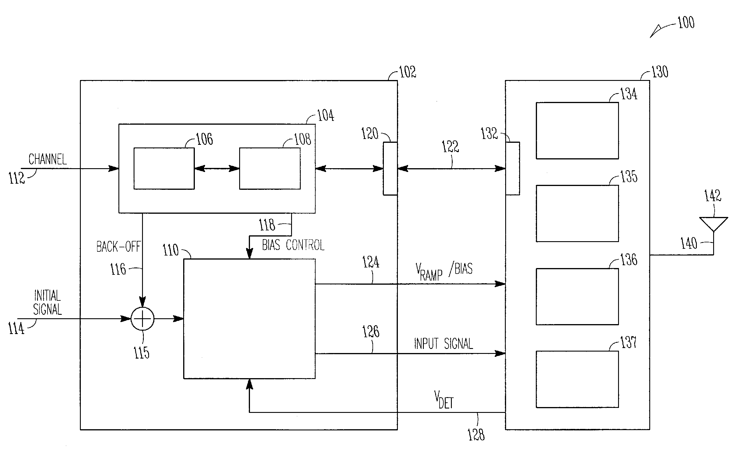
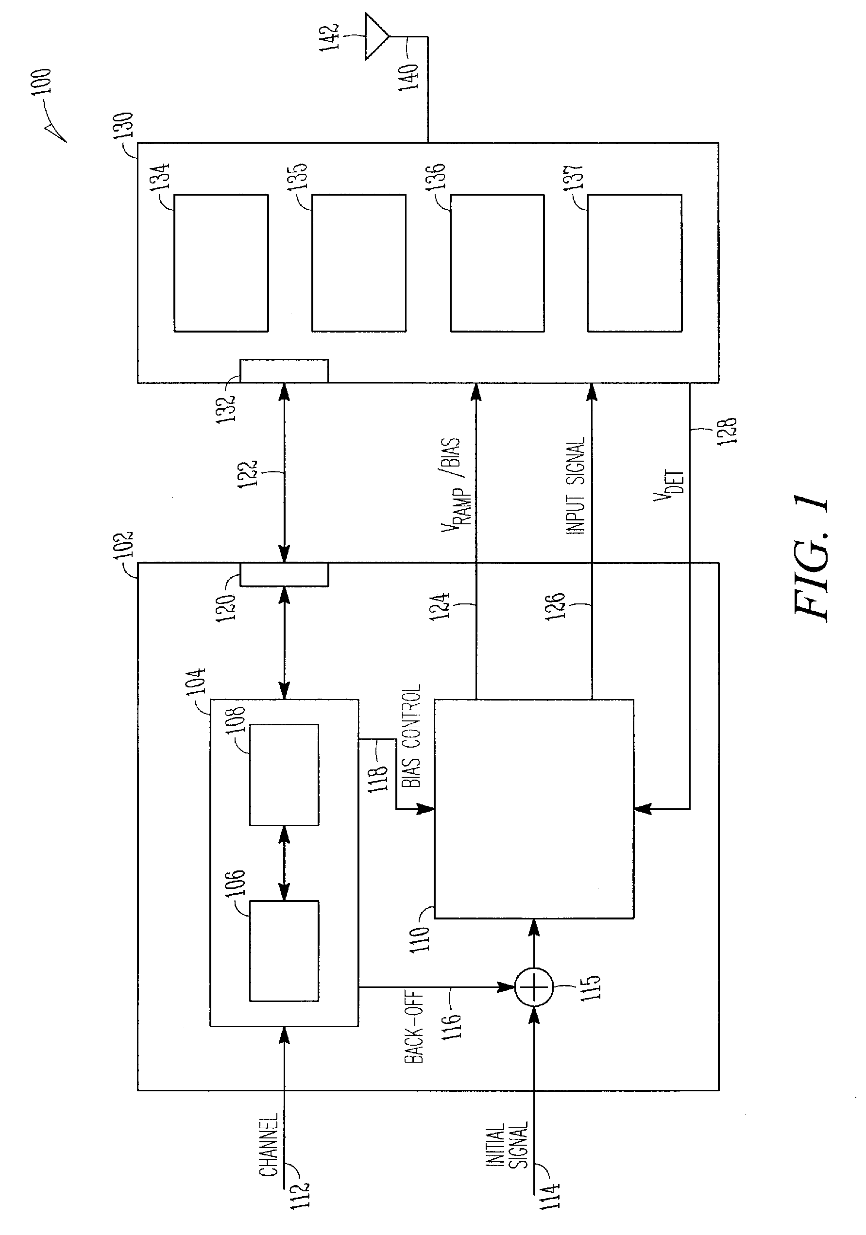
[0008]The growth and use of radio-frequency devices (such as hand-held devices) with increasing functional capabilities (e.g., voice, video, and data) has resulted in a greater demand for efficient power-saving techniques to increase the battery life in these devices. Energy-efficient linear power amplifiers are essential components in mobile battery operated systems having wireless connec...


PUM


Abstract

Some embodiments discussed relate to an apparatus comprising a power amplifier module. The power amplifier module includes a plurality of sensors, and a first digital communication port configured to provide a monitor signal from at least one of the plurality of sensors. The apparatus includes a transceiver module coupled to provide an signal to an input of the power amplifier the transceiver module including a second digital communication port configured to receive the monitor signal from the first digital communication port, a processing unit configured to generate at least one of a bias control signal and a back-off signal dependent upon the monitor signal, and a power controller to receive the at least one of bias control signal and the back-off signal and provide at least one further input signal to the power amplifier based on at least one of the bias control signal and the back-off signal.

Description

RELATED APPLICATIONS[0001]This patent application claims the benefit of priority, under 35 U.S.C. Section 119(e), to U.S. Provisional Patent Application Ser. No. 60 / 863,483, filed on Oct. 30, 2006, which is incorporated herein by reference.TECHNICAL FIELD[0002]Embodiments described herein relate generally to power amplifiers and more particularly, to optimizing the output power levels in power amplifiers.BACKGROUND[0003]Global System for Mobile Communications (GSM) is one of the standards used for mobile phones. Gaussian Minimum Shift Keying (GMSK) is a type of continuous-phase frequency-shift keying used in GSM. Enhanced Data rates for GSM Evolution (EDGE) is a digital mobile technology used in conjunction with GSM to provide packet-switched applications such as internet connection. EDGE additionally uses 8 phase-shift keying (8PSK) as part of the modulation and coding scheme.BRIEF DESCRIPTION OF THE DRAWINGS[0004]FIG. 1 illustrates a schematic view of an apparatus for optimizing t...

Claims


Application Information

Patent Timeline
Patent Type & Authority Patents(United States)
IPC IPC(8): H01Q11/12
CPCH04B1/0475
Inventor CAMUFFO, ANDREALANGER, ANDREAS
Owner INTEL CORP
Features
  • R&D
  • Intellectual Property
  • Life Sciences
  • Materials
  • Tech Scout
  • Unparalleled Data Quality
  • Higher Quality Content
  • 60% Fewer Hallucinations
Learn More