Thin film deposition via charged particle-depleted plasma achieved by magnetic confinement

a technology of magnetic confinement and thin film, applied in the direction of plasma technique, chemical vapor deposition coating, coating, etc., can solve the problems of thin film products, rigidity and inability to carry heavy weight, and low separation between plasma constituents, so as to facilitate extinguishing or depletion, reduce the effect of separation and reduction of separation

Inactive Publication Date: 2011-09-13
OVSHINSKY TECH
View PDF6 Cites 1 Cited by
  • Summary
  • Abstract
  • Description
  • Claims
  • Application Information

AI Technical Summary

Benefits of technology

[0014]The instant invention provides a method and apparatus for the plasma deposition of thin film materials. In one embodiment, the invention is directed at the plasma deposition of photovoltaic materials at high deposition rates with improved photovoltaic efficiency. The invention recognizes that the plasmas used in prior art deposition processes are unrefined and include ionized species that are detrimental to photovoltaic efficiency. In the invention, a plasma formed from one or more precursors is manipulated with a magnetic field to provide a deposition medium more conducive to the formation of thin film or photovoltaic materials having a low defect concentration in the as-deposited state.
[0015]In the instant invention, a plasma is formed from one or more deposition precursors and its composition is controlled to provide a deposition medium having an optimized distribution of growth species adjacent to the deposition surface. The characteristics of the plasma are controlled by a magnetic field that is configured to reduce the concentration of ionized species and increase the concentration of neutral species. Neutral species include charge-neutral molecules and charge-neutral free radicals. In one embodiment, the magnetic field increases the concentration of neutral species in the plasma relative to ionized species. In another embodiment, the magnetic field increases the concentration of excited state neutral species in the plasma relative to ionized species. Enrichment of the plasma with neutral species promotes the formation of as-deposited thin film materials by reducing the presence of ionized species and avoiding deleterious interactions between ionized species and the thin film material.
[0018]In one embodiment, magnetic manipulation of the plasma includes restricting the spatial dimensions of the plasma. Restriction of spatial dimensions may include confining the plasma to a particular spatial region or controlling the shape of the plasma region. In one embodiment, a magnetic field is used to compress the plasma at one or more positions so that the average separation between the constituents of the plasma is decreased. The reduced separation promotes extinguishment or depletion of charged or ionized species and facilitates enrichment of the plasma with neutral or excited state neutral species to form a deposition medium.

Problems solved by technology

Unless solar energy becomes cost competitive with fossil fuels, however, society will lack the motivation to eliminate its dependence on fossil fuels and will refrain from adopting solar energy on the scale necessary to meaningfully address global warming.
Crystalline silicon, however, possesses weak absorption of solar energy because it is an indirect gap material.
As a result, photovoltaic modules made from crystalline silicon are thick, rigid and not amenable to lightweight, thin film products.
One problem with current plasma-deposited photovoltaic materials is the presence of a high concentration of intrinsic defects in the as-deposited state.
The intrinsic defects include structural defects (e.g. dangling bonds, strained bonds, unpassivated surface states, non-tetrahedral bonding distortions, coordinatively unsaturated silicon or germanium) that create electronic states within the bandgap of the photovoltaic material.
It has been observed that the concentration of intrinsic defects increases as the deposition rate of amorphous silicon-based photovoltaic increases.
The low deposition rates needed to achieve high photovoltaic efficiency limit the economic competiveness of conventional plasma deposition processes.

Method used


Image

  • Thin film deposition via charged particle-depleted plasma achieved by magnetic confinement
  • Thin film deposition via charged particle-depleted plasma achieved by magnetic confinement
  • Thin film deposition via charged particle-depleted plasma achieved by magnetic confinement

Examples


Embodiment Construction

[0025]Although this invention will be described in terms of certain preferred embodiments, other embodiments that are apparent to those of ordinary skill in the art, including embodiments that do not provide all of the benefits and features set forth herein and including embodiments that provide positive benefits for high-volume manufacturing, are also within the scope of this invention. Accordingly, the scope of the invention is defined only by reference to the appended claims.

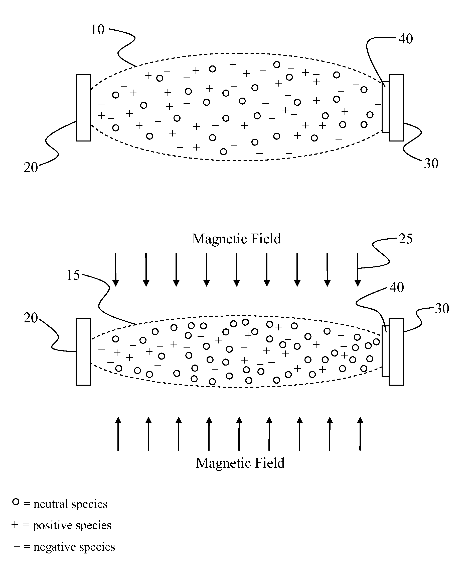
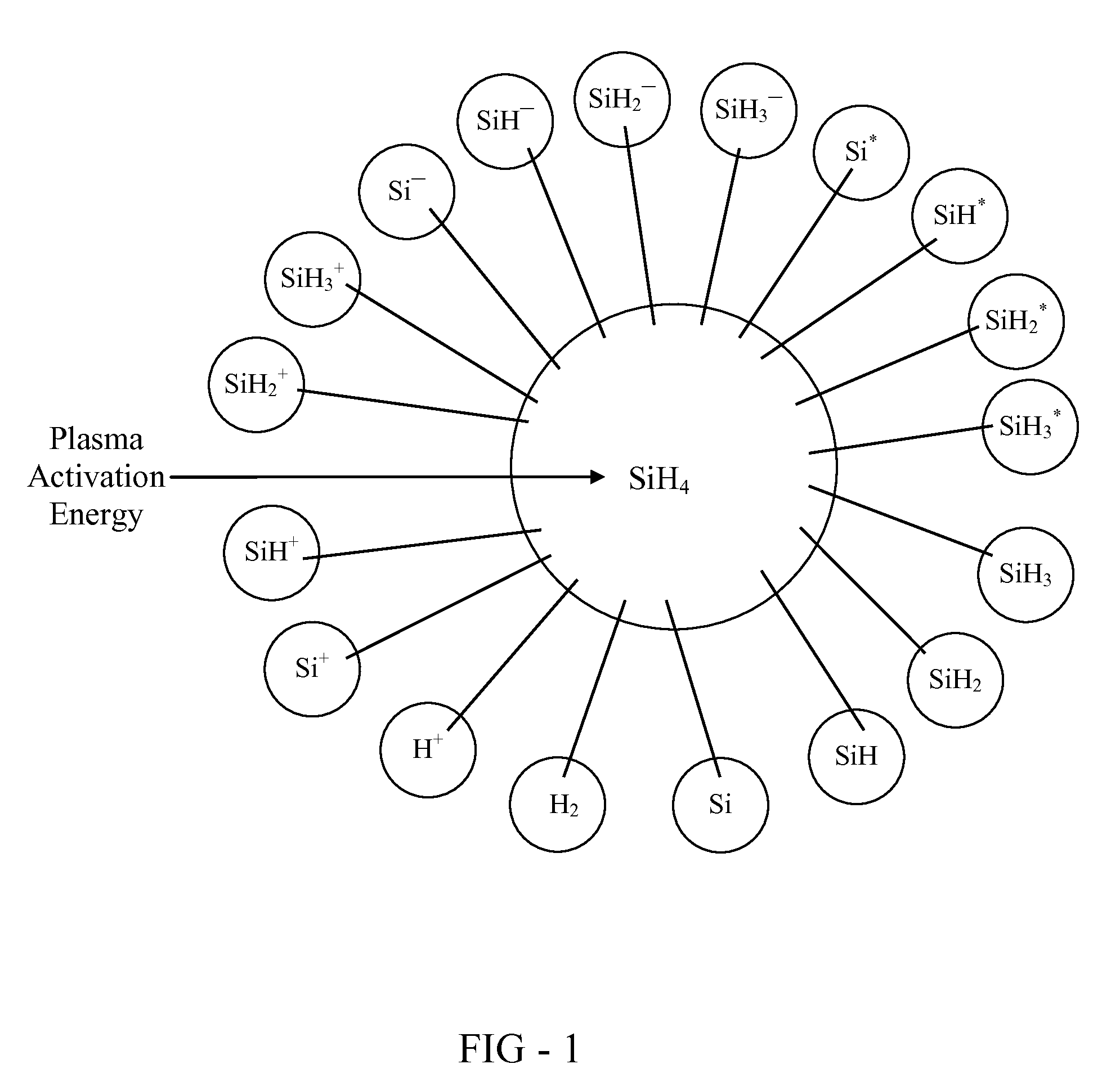
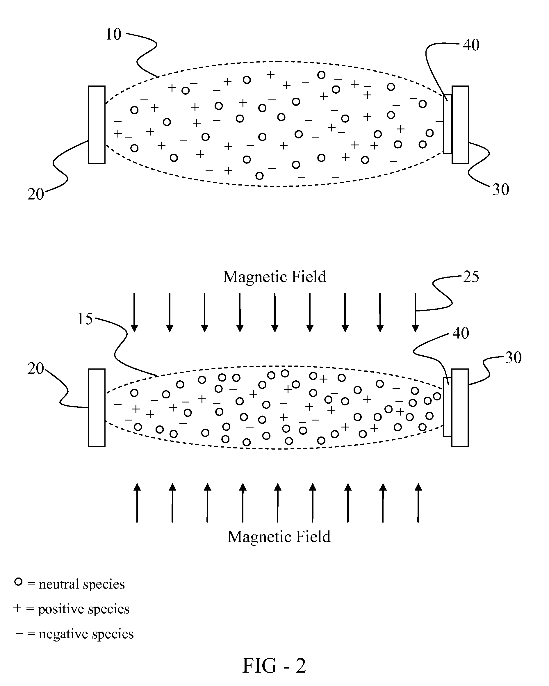
[0026]The instant invention focuses on a plasma deposition process in which the state of the plasma is engineered to optimize the structural and electronic quality of an as-deposited thin film material. In one embodiment, the thin film material is a photovoltaic material. The invention is designed to remedy conditions present in plasmas used in conventional plasma deposition processes that impair the performance of an as-deposited photovoltaic material.

[0027]In a plasma deposition process, a plasma is normall...


PUM

PropertyMeasurementUnit
magnetic fieldaaaaaaaaaa
concentrationaaaaaaaaaa
defect concentrationaaaaaaaaaa

Abstract

A method and apparatus for forming thin film materials via a plasma deposition process in the presence of a magnetic field. A precursor is delivered to a deposition chamber and activated to form a plasma. The plasma may be initiated in the presence of a magnetic field or subjected to a magnetic field after initiation. The plasma includes ionized and neutral species derived from the precursor and the magnetic field manipulates the plasma to effect a reduction in the population of ionized species and an enhancement of the population of neutral species. A thin film material is subsequently formed from the resulting neutral-enriched deposition medium. The method permits formation of thin film materials having a low density of defects. In one embodiment, the thin film material is a photovoltaic material and the suppression of defects leads to an enhancement in photovoltaic efficiency.

Description

FIELD OF INVENTION[0001]This invention relates to the deposition of thin film materials using an intermediate plasma. More particularly, this invention relates to deposition of thin films using an intermediate magnetically-controlled plasma. Most particularly, this invention relates to deposition of photovoltaic materials from a charged particle-depleted deposition medium obtained through magnetic manipulation of a plasma.BACKGROUND OF THE INVENTION[0002]Concern over the depletion and environmental impact of fossil fuels has stimulated strong interest in the development of alternative energy sources. Significant investments in areas such as batteries, fuel cells, hydrogen production and storage, biomass, wind power, algae, and solar energy have been made as society seeks to develop new ways of creating and storing energy in an economically competitive and environmentally benign fashion. The ultimate objective is to minimize society's reliance on fossil fuels and to do so in an econo...

Claims


Application Information

Patent Timeline
Patent Type & Authority Patents(United States)
IPC IPC(8): H05H1/02
CPCH01L21/0262C23C16/44C23C16/452C23C16/50H01L21/02532H01J37/32009H01J37/32192H01J37/32761C23C16/511Y02E10/50H01L31/18H01L31/042
Inventor OVSHINSKY, STANFORD R.
Owner OVSHINSKY TECH
Why Eureka
Try Eureka