Polymerization device

a technology of polymerization device and plastic, which is applied in the direction of x-ray tube, light therapy, optical radiation measurement, etc., can solve problems such as compact design

Inactive Publication Date: 2011-09-13
IIE
View PDF4 Cites 1 Cited by
  • Summary
  • Abstract
  • Description
  • Claims
  • Application Information

AI Technical Summary

Benefits of technology

[0003]It is the objective of the invention to provide a device for polymerization of plastics that may be hardened by UV irradiation whose irradiation source possesses improved energy efficiency in comparison with conventional discharge lamps, and whose hardening performance is adequately great. The irradiation source must also be of compact design.
[0005]It has been found that not only UV irradiation is responsible for the hardening of plastics. The UV irradiation initiates the polymerization process and maintains it. The speed of the polymerization process, however, does not only depend on the UV irradiation. The polymerization speed is, in turn, dependent on the temperature. The additional influence of infra-red (IR) irradiation correspondingly raises the temperature. Very localized temperature increases may be caused with the help of an IR emitter, which has shown to be significantly more efficient than, for example, the increase of ambient temperature in a tunnel oven. By loading the plastic to be hardened with UV and IR irradiation, only the specific area to be hardened is heated. In this manner, even stronger heating of the plastic may be achieved than in a tunnel oven since the entire body needs not be increased in temperature, but rather only a localized area is heated that immediately cools after irradiation.
[0006]A solid-state laser that emits in the UV spectrum may be so designed that it achieves the required power output, yet is of compact design. This is possible only with simultaneous application of an IR emitter since the UV power required is thereby reduced. A solid-state laser is associated with relatively lower manufacturing cost.
[0008]A conventional IR emitter may be used as the source of IR emission. Such an IR emitter projects a field onto the plastic to be hardened that is not sharply delineated. The emission pattern of the IR emission source and of the UV should be overlapped in the case such that articles to be dried first pass through the field of the IR emission source and the plastic being hardened has sufficient time to be heated. The line-shaped pattern of the UV emission source should therefore be positioned within the area of the IR field in which the articles to be dried enter immediately after leaving the IR field. It may thus be ensured that the plastic to be hardened upon entry to the UV emission pattern is at a temperature that ensures rapid and positive drying of the plastic to be hardened.
[0009]The IR emission source also advantageously projects a line-shaped emission pattern on the plastic to be hardened. The two line-shaped emission patterns load the plastic to be hardened only for a very brief period with the necessary UV and IR energy. Since an exceedingly brief irradiation effect is involved, one may work with very high energy levels. The plastic may be brought to a higher temperature for a very brief period without damaging it than with the use of a conventional IR emitter. The hardening speed may thus be increased even more.
[0010]The IR emitter advantageously possesses a diode laser to generate the line-shaped emission pattern. Diode lasers that irradiate in the IR spectrum are of very high performance, and may also be manufactured at very low cost.

Problems solved by technology

A solid-state laser that emits in the UV spectrum may be so designed that it achieves the required power output, yet is of compact design.

Method used


Image

  • Polymerization device
  • Polymerization device

Examples


Embodiment Construction

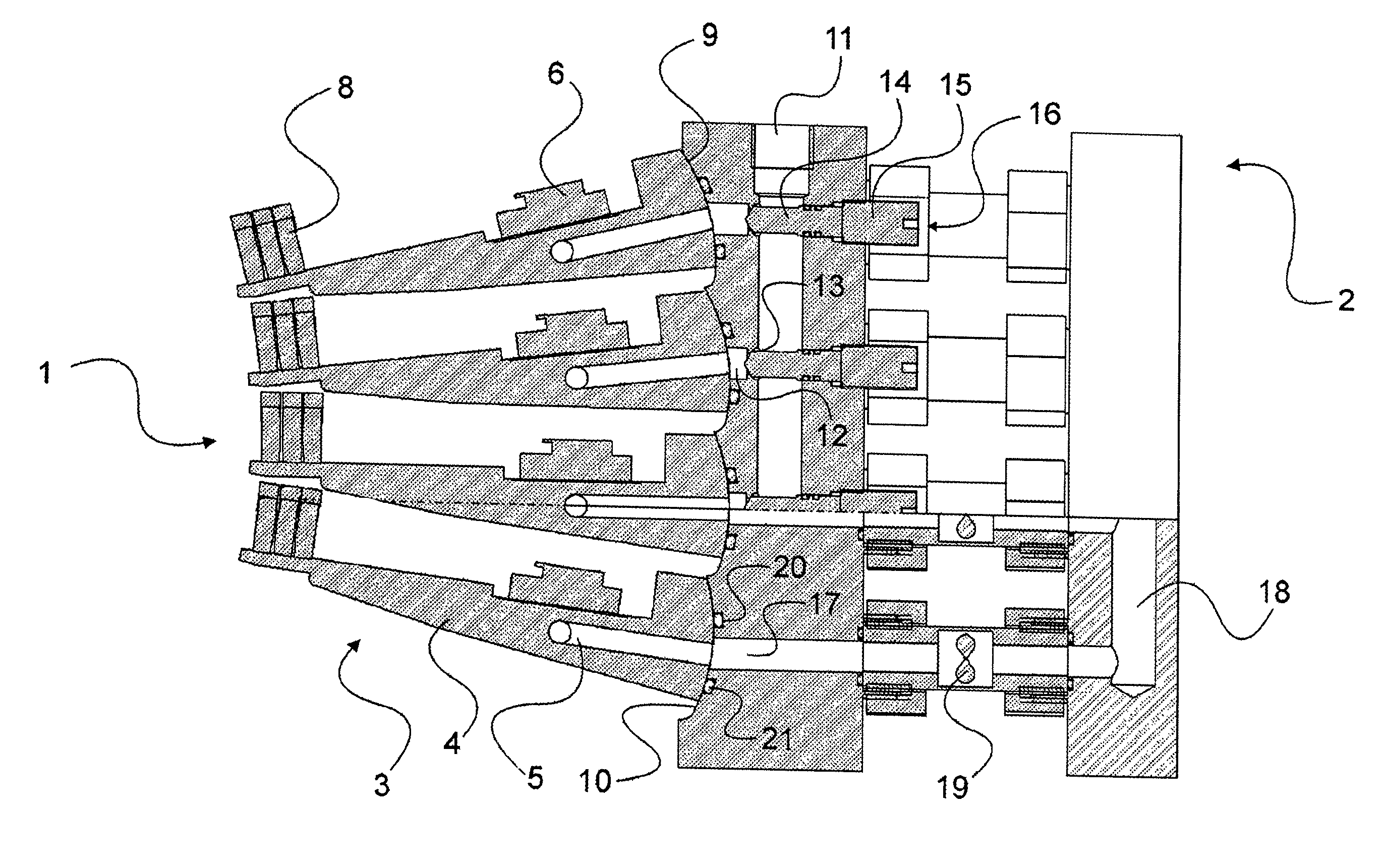
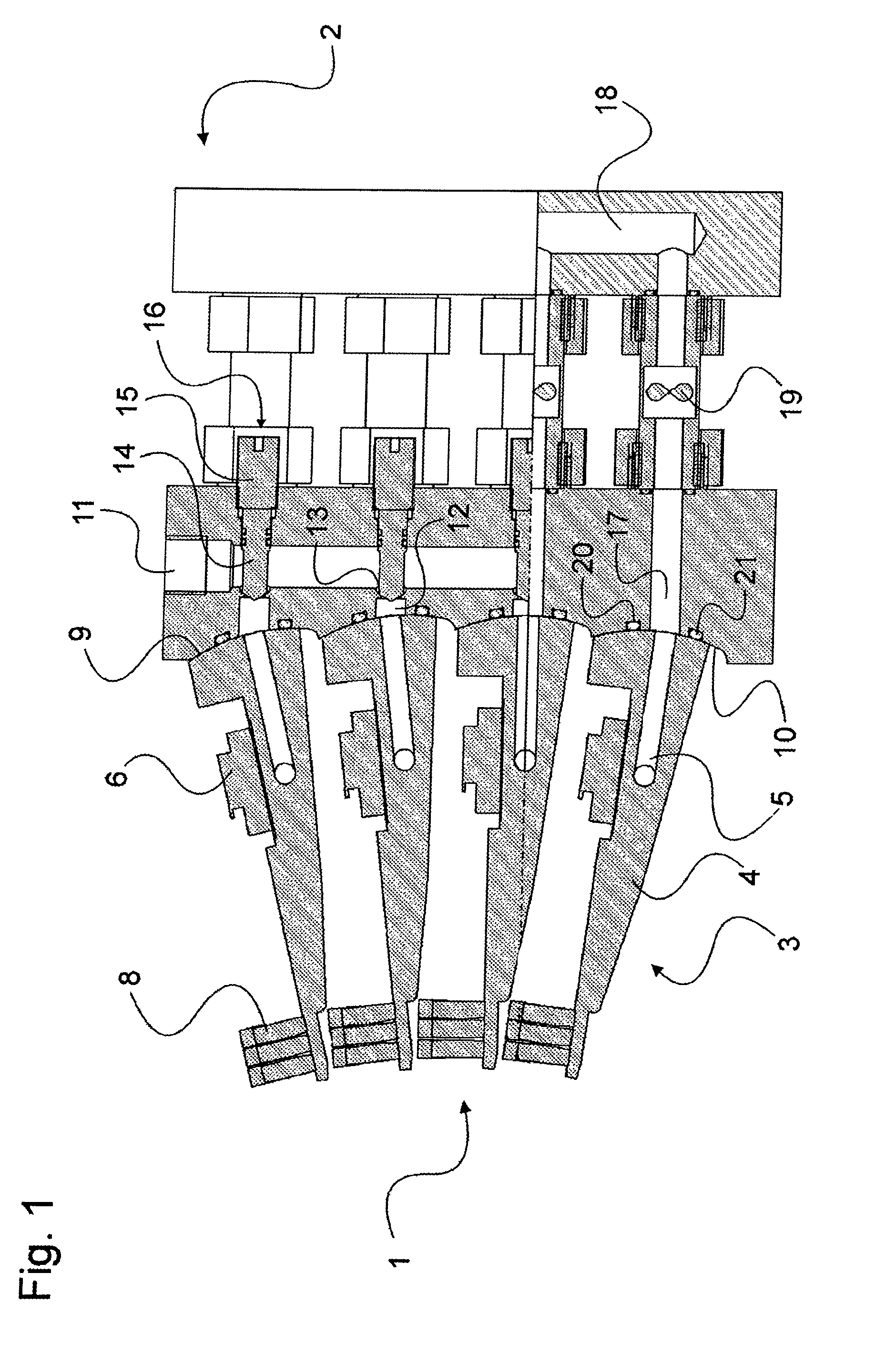
[0017]The preferred embodiment of the present invention will now be described with reference to FIG. 1 of the drawing.

[0018]FIG. 1 shows a laser module 1, a single mounting unit 2, and four laser units 3 mounted on it. Each laser unit 3 includes a base unit 4 within which coolant channels 5 extend, a laser-diode bar 6 mounted on the base unit 4, and a collecting lens 8. The base unit 4 includes a curved adjustment surface 9 on the side opposite the collecting lens 8 that lies flat on an identically-curved mounting surface 10. The mounting surface 10 is a component of the mounting unit 2. Each laser unit 3 is mounted in the vicinity of the collecting lens 8 so that it may pivot about an axis (not shown), and is affixed in the area of the adjustment surface 9 and the mounting surface 10 by means of screws (not shown) so that it may be removed.

[0019]Each curved adjustment surface 9 and each mounting surface 10 is formed as a section of a cylinder. Its radius here corresponds to the sep...


PUM

PropertyMeasurementUnit
emission spectrumaaaaaaaaaa
poweraaaaaaaaaa
energy efficiencyaaaaaaaaaa

Abstract

A device to polymerize plastics that are to be hardened by means of UV irradiation comprises two different irradiation sources for UV irradiation and IR irradiation, respectively, whose irradiation is projected onto the plastic to be hardened. The irradiation source for the UV irradiation includes a solid-state laser.

Description

BACKGROUND OF THE INVENTION[0001]The invention relates to a device to polymerize plastics to be hardened by ultraviolet (UV) irradiation.[0002]Such devices have become known especially for the hardening of paints and inks on any surface. For this, discharge lamps are usually used that possess an emission spectrum including a more or less major component in the UV realm. Developments in this area tend toward increasing the UV component of these discharge lamps in order to be able to reduce the power requirement of the discharge lamps while maintaining the same UV output level. There has already been consideration of using laser irradiation in the UV spectrum for this hardening. Laser sources such as Excimer lasers, that have received consideration for this application because of their power output, are entirely too large and too expensive for this purpose.SUMMARY OF THE INVENTION[0003]It is the objective of the invention to provide a device for polymerization of plastics that may be ...

Claims


Application Information

Patent Timeline
Patent Type & Authority Patents(United States)
IPC IPC(8): G01N21/00G01N21/33G01N21/35
CPCB01J19/121B01J19/123B01J19/128B01J2219/0801B01J2219/0879
Inventor KRESS, EKKEHARD
Owner IIE
Why Eureka
Try Eureka