Sintered glass and glass-ceramic structures and methods for producing

a technology of glass-ceramic and sintering glass, which is applied in the direction of glass reforming apparatus, microstructural devices, printing, etc., can solve the problems of weak spots and potential breakage points in the final fully sintered product, and achieve the effect of more robust structure and easy manufacturing

Active Publication Date: 2011-09-20
CORNING INC
View PDF10 Cites 5 Cited by
  • Summary
  • Abstract
  • Description
  • Claims
  • Application Information

AI Technical Summary

Benefits of technology

[0007]The invention includes, according to one embodiment, a unitary structure comprised of two or more planar substrates fused together by a glass or glass-ceramic sintered patterned frit material disposed therebetween. The pattern of the sintered patterned frit material defines passages therein, and the sintered patterned frit material has a characteristic first minimum feature size in a direction parallel to the substrates. Particles of the frit material have a poly-dispersed size distribution up to a maximum frit particle size, in a maximum length dimension, and the first minimum feature size of the sintered patterned frit material is greater than 2 times the maximum frit particle size, desirably about 3 times or more, and less than 6.25 times the maximum frit particle size, desirably about 5 times or less, most desirably about 4 times or less. Setting the minimum feature size sufficiently low relative to the maximum frit particle size makes the structure more robust by preventing crack formation, while keeping it sufficiently high makes the structure more easily manufactured by assuring sufficient resolution in useful forming processes such as molding.

Problems solved by technology

Challenges exist, however, in providing high strength in the final device over a range of feature sizes of the patterned frit material.
This results in weak spots, points of potential breakage in the final fully sintered product.

Method used


Image

  • Sintered glass and glass-ceramic structures and methods for producing
  • Sintered glass and glass-ceramic structures and methods for producing
  • Sintered glass and glass-ceramic structures and methods for producing

Examples


Embodiment Construction

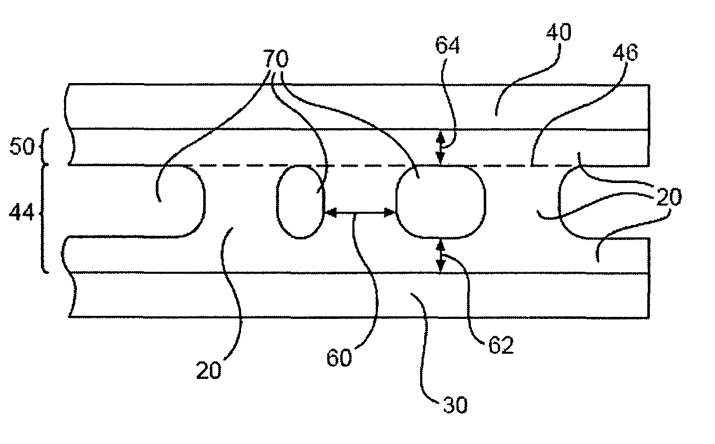
[0017]Microfluidic devices, such as device 10 of FIG. 1, may be comprised of a three-dimensional (3-D) sintered frit structure 20 that is sintered and thereby fused between two substrates 30 and 40 so as to define a monolithic device 10 with fluidic passages 70 therein. In some devices or portions of devices, as in the device 10 represented in FIG. 1, one layer 44 of 3-D frit structure is formed, desirably by molding, on a substrate, then sintered to another substrate having only a thin flat layer of frit 50, resulting in a fused joint within the 3-D frit structure 20, indicated by the dashed line 46. Alternatively, on other devices or portions of devices, two 3-D frit structures first formed on separate substrates may be sintered to each other.

[0018]In either case, the resulting patterned sintered frit structure 20 has a characteristic minimum feature size or dimension 60 in the direction parallel to the substrates 30, 40. Dimension 60 corresponds to the characteristic minimum dist...


PUM

PropertyMeasurementUnit
particle sizeaaaaaaaaaa
widthaaaaaaaaaa
widthaaaaaaaaaa

Abstract

A unitary structure (10) is comprised of two or more planar substrates (30, 40) fused together by a glass or glass-ceramic sintered frit structure (20) disposed therebetween. The pattern of the sintered patterned frit material defines passages (70) therein, and the sintered frit structure (20) has a characteristic minimum feature size (60) in a direction parallel to the substrates. Particles of the frit material have a poly-dispersed size distribution up to a maximum frit particle size, in a maximum length dimension, and the minimum feature size or dimension (60) of the sintered patterned frit material is greater than 2 times the maximum frit particle size, desirably about 3 times or more, and less than 6.25 times the maximum frit particle size, desirably about 5 times or less, most desirably about 4 times or less. A method for making the structure (10) is also disclosed.

Description

PRIORITY[0001]This application is claiming the priority of: European Patent Application Number 06300471.7 filed May 15, 2006, titled SINTERED GLASS AND GLASS-CERAMIC STRUCTURES AND METHODS FOR PRODUCING.BACKGROUND OF THE INVENTION[0002]1. Field of the Invention[0003]The present invention relates generally to sintered glass and glass-ceramic structures and methods for their formation, and particularly sintered glass and glass-ceramic structures formed on a solid substrate and methods for formation of such.[0004]2. Technical Background[0005]One useful fabrication method for the formation of glass or glass-ceramic structures, such as glass or glass-ceramic structures for use as fluidic or microfluidic devices, is to form a relatively fine 3-D structure, such as walls defining fluidic passages of a fluidic or microfluidic device, by shaping a glass frit and binder mixture, on or onto a substrate. The substrate and frit together may then be stacked, with one or more other substrates each...

Claims


Application Information

Patent Timeline
Patent Type & Authority Patents(United States)
IPC IPC(8): B32B3/00G03G7/00B32B1/00C04B33/34B32B3/12B44C1/17B32B7/14B32B7/00B32B17/00B32B18/00B41M5/00C03B29/00B32B3/20B01L99/00B01L3/00C03C8/00
CPCB81C1/00071C03C17/04C03C27/06C03C27/10B01L3/5027B81C2201/019Y10T29/494Y10T428/24926Y10T428/24562Y10T428/24851Y10T428/24661Y10T428/24744Y10T428/24802Y10T137/2224B01J19/00G01N1/00
Inventor NEDELEC, YANN P M
Owner CORNING INC
Why Eureka
Try Eureka