RFID cargo/storage container tamper seal
a cargo/storage container and tamper seal technology, applied in the direction of instruments, electrical signalling details, burglar alarm mechanical actuation, etc., can solve the problems of inability to realize long-distance transmission, inconvenient installation, and high cost of active rfid tamper seals, etc., to achieve the effect of convenient installation
- Summary
- Abstract
- Description
- Claims
- Application Information
AI Technical Summary
Benefits of technology
Problems solved by technology
Method used
Image
Examples
first embodiment
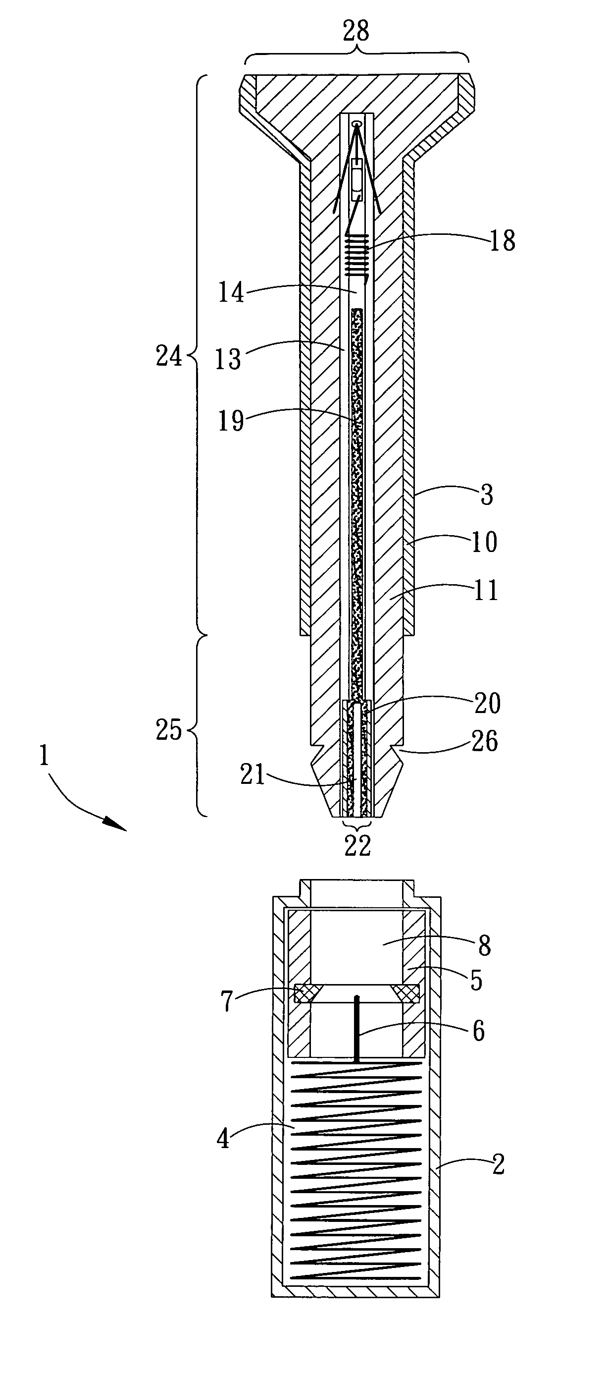
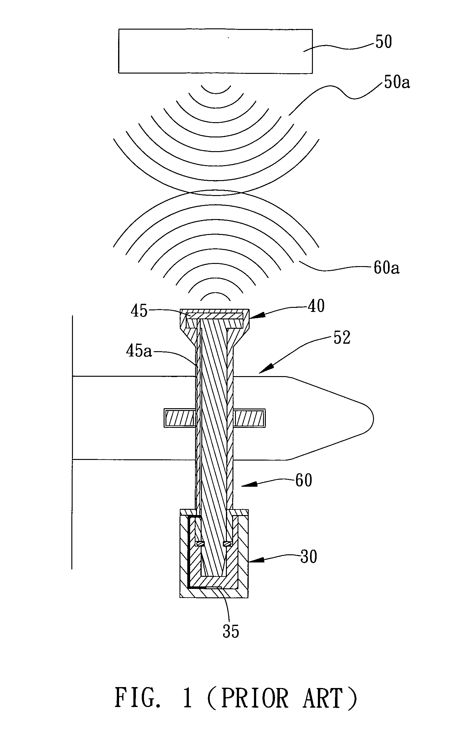
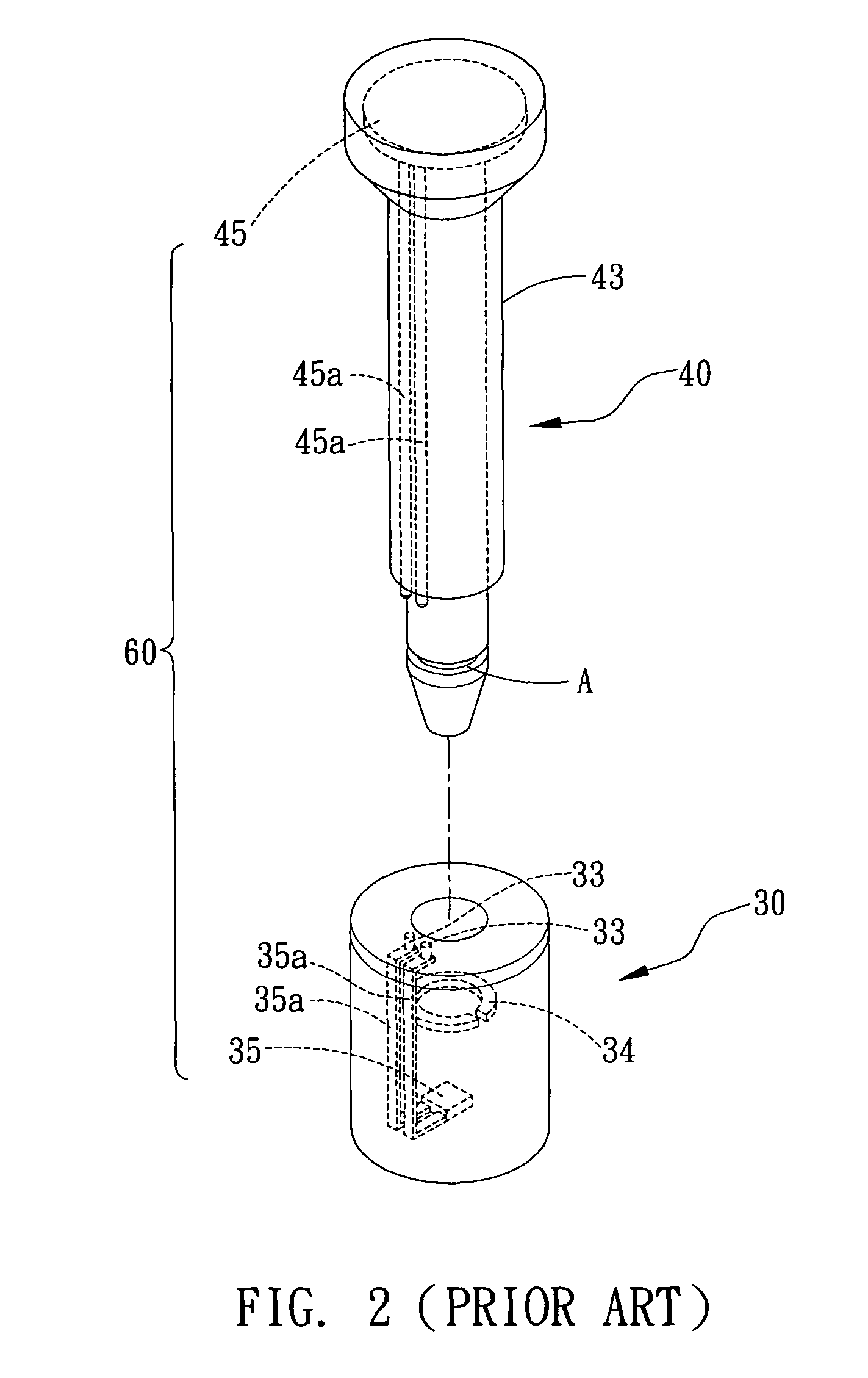
[0028]FIG. 4 depicts the RFID tamper seal of the present invention, which is applicable to Customs safety inspection / automated clearance systems equipped with RFID readers, the RFID tamper seal being adapted to install on the doorbolt latches of a container, so that when a container vehicle passes an inspection system at Customs, the RFID tamper seal(s) transmit a frequency signal containing identification information to enable the inspection system to read and record the identification information in real time. The RFID tamper seal consists of an insulating main body 2, a rod portion 3, an antenna 4, a metal ring 5 and a circuit module 14. The following descriptions provide the details of each constituent component of the RFID tamper seal 1.
[0029]Again referring to FIG. 4, the main body 2 of the RFID tamper seal 1 is a casing body made of insulating material, wherein the insulating material may include—but is not limited to—Teflon or polyethylene electrical insulating material for ...
second embodiment
[0035]FIG. 6 is an assembled cross-sectional view showing the RFID tamper seal in accordance with the present invention. This embodiment differs from the first one only in that it comprises a metal cap 23, and thus, the detailed description of the other constituent components is omitted for brevity. Also, FIG. 6 illustrates only the rod portion 3 of the RFID tamper seal of the invention for brevity and in order to distinguish the difference. As shown, the rod portion 3 is preformed with an opening 29, wherein, upon assembly, the circuit module 14 is pushed into the opening 29 formed at the bottom of the rod portion 3. Then, the opening 29 is sealed by the metal cap 23.
[0036]FIG. 7 is a cross-sectional view showing the RFID tamper seal depicted in FIG. 6 after complete assembly. As shown, the rod portion 3, after insertion into the insulating main body 2, is tightly engaged with the C-shaped ring 7 of the insulating main body, and the antenna probe 6 extending from the antenna 4 is i...
PUM
 Abstract
Description
Claims
Application Information
 - R&D
- Intellectual Property
- Life Sciences
- Materials
- Tech Scout
- Unparalleled Data Quality
- Higher Quality Content
- 60% Fewer Hallucinations
Browse by: Latest US Patents, China's latest patents, Technical Efficacy Thesaurus, Application Domain, Technology Topic, Popular Technical Reports.
© 2025 PatSnap. All rights reserved.Legal|Privacy policy|Modern Slavery Act Transparency Statement|Sitemap|About US| Contact US: help@patsnap.com


