Exhaust system for a motorcycle, and motorcycle incorporating same

a technology for exhaust systems and motorcycles, applied in the direction of machines/engines, cycles, transportation and packaging, etc., can solve the problems of disadvantageous lengthening of exhaust systems in longitudinal directions of vehicles, disadvantageous lengthening of exhaust systems, and increased wheelbase of motorcycles, so as to reduce the length of exhaust systems including silencers, reduce the wheelbase of motorcycles, and increase the lateral width of each of the muffler chambers.

Active Publication Date: 2011-10-11
HONDA MOTOR CO LTD
View PDF15 Cites 9 Cited by
  • Summary
  • Abstract
  • Description
  • Claims
  • Application Information

AI Technical Summary

Benefits of technology

[0019]In the present invention according to the first aspect—since the exhaust pipes converge below the engine and connected to the first muffler chamber, the second muffler chamber disposed parallel to the first muffler chamber, the silencer is arranged in the rear of the body of the second muffler chamber in the longitudinal direction, the exhaust gas from the second muffler chamber flows into the silencer, and is emitted outside—the length of the exhaust pipes and that of the silencer can be possibly reduced by securing the length of the exhaust pipes and by first arranging the muffler chambers parallel to the right and left. Accordingly, the length of the exhaust system including the silencer is reduced. As a result, the wheelbase of the motorcycle can be reduced.
[0020]Besides, since the first muffler chamber and the second muffler chamber are arranged parallel to each other, the mass of the exhaust system arranged below the engine is centralized. Accordingly, a balanced exhaust system arranged below the engine can be acquired.
[0021]Further, in the present invention, since the first muffler chamber and the second muffler chamber are arranged parallel to each other, the lateral width of each of the muffler chambers can be increased, while reducing the longitudinal length thereof, as described above. Therefore, height of each of the muffler chambers can be decreased (inhibited) without compromising capacity of the muffler chambers. Also, since the height of the muffler chamber is decreased, the minimum road clearance can be sufficiently secured while arranging the exhaust system below the engine.
[0022]In the present invention according the second aspect thereof, in addition to the first aspect—since exhaust gas flows into the rear of the second muffler chamber in the vehicle width direction, and then flows in the longitudinal direction of the vehicle body in the second muffler chamber, which then turned back in the front in the longitudinal direction of the body of the second muffler chamber and flows rearwardly in the longitudinal direction of the body, and then flows into the silence from a front portion thereof in the longitudinal direction of the vehicle body and is subsequently, emitted outside the exhaust system from the rear of the silencer—the length of the exhaust pipes can be reduced while securing the required sufficient volume of the exhaust system piping for treating and emitting exhaust gas from the engine. Also, efficiency of the exhaust system can be increased providing excellent output. Further, desired silencing effects for the exhaust system can be acquired.
[0023]In the present invention according the third aspect thereof, since the plural exhaust pipes are inserted into the first muffler chamber and are unified therein, and since the catalyst is arranged in the junction (or vicinity thereof) where the plural pipes are connected, the mass below the engine can be centralized.
[0024]In the present invention according to the fourth aspect thereof, since the first muffler chamber and the second muffler chamber are arranged distributively at the left and right sides (of the center line along the longitudinal direction) in the vehicle width direction—effective balance in the lateral arrangement of the exhaust system is achieved.

Problems solved by technology

Since the exhaust pipes and connecting / collecting pipes are arranged on one side and the mufflers (having large volumes) are arranged on the other side, the length of the exhaust system in a longitudinal direction of the vehicle is disadvantageously lengthened (increased), particularly when the exhaust system is arranged below the engine of the motorcycle, the length of the exhaust system is further increased.
As a result of increasing a length of the exhaust system, arranged below the engine in the longitudinal direction of the vehicle, a wheelbase of the motorcycle is disadvantageously increased.

Method used


Image

  • Exhaust system for a motorcycle, and motorcycle incorporating same
  • Exhaust system for a motorcycle, and motorcycle incorporating same
  • Exhaust system for a motorcycle, and motorcycle incorporating same

Examples


Embodiment Construction

[0030]It should be understood that only structures considered necessary for illustrating selected embodiments of the present invention are described herein. Other conventional structures, and those of ancillary and auxiliary components of the system, will be known and understood by those skilled in the art.

[0031]An illustrative embodiment of the present invention is described below with reference to the attached drawings. In the drawings, Fr denotes a front traveling direction of a vehicle, Rr denotes the rear direction opposite to the front traveling direction, R denotes the right side based upon a rider's position, while normally operating the vehicle, and L denotes the left side based upon the rider's position.

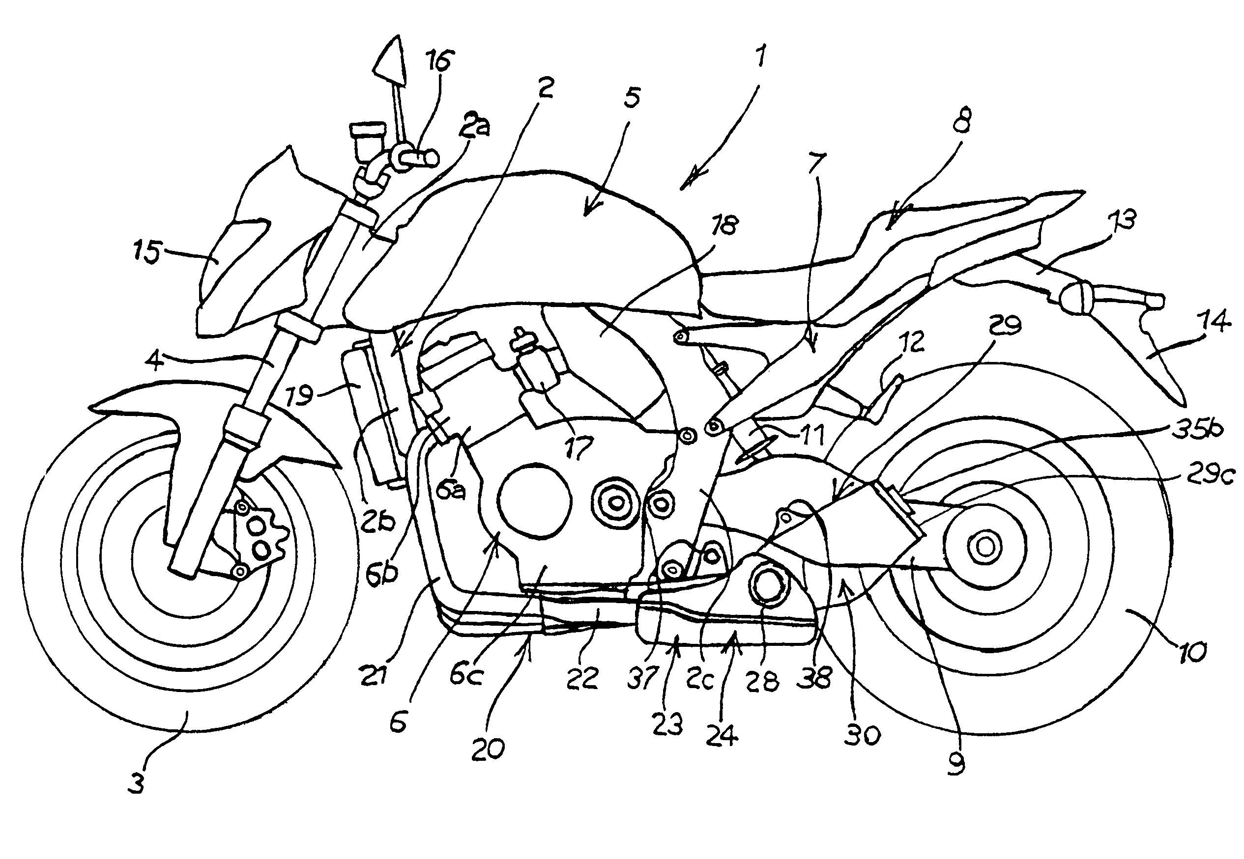
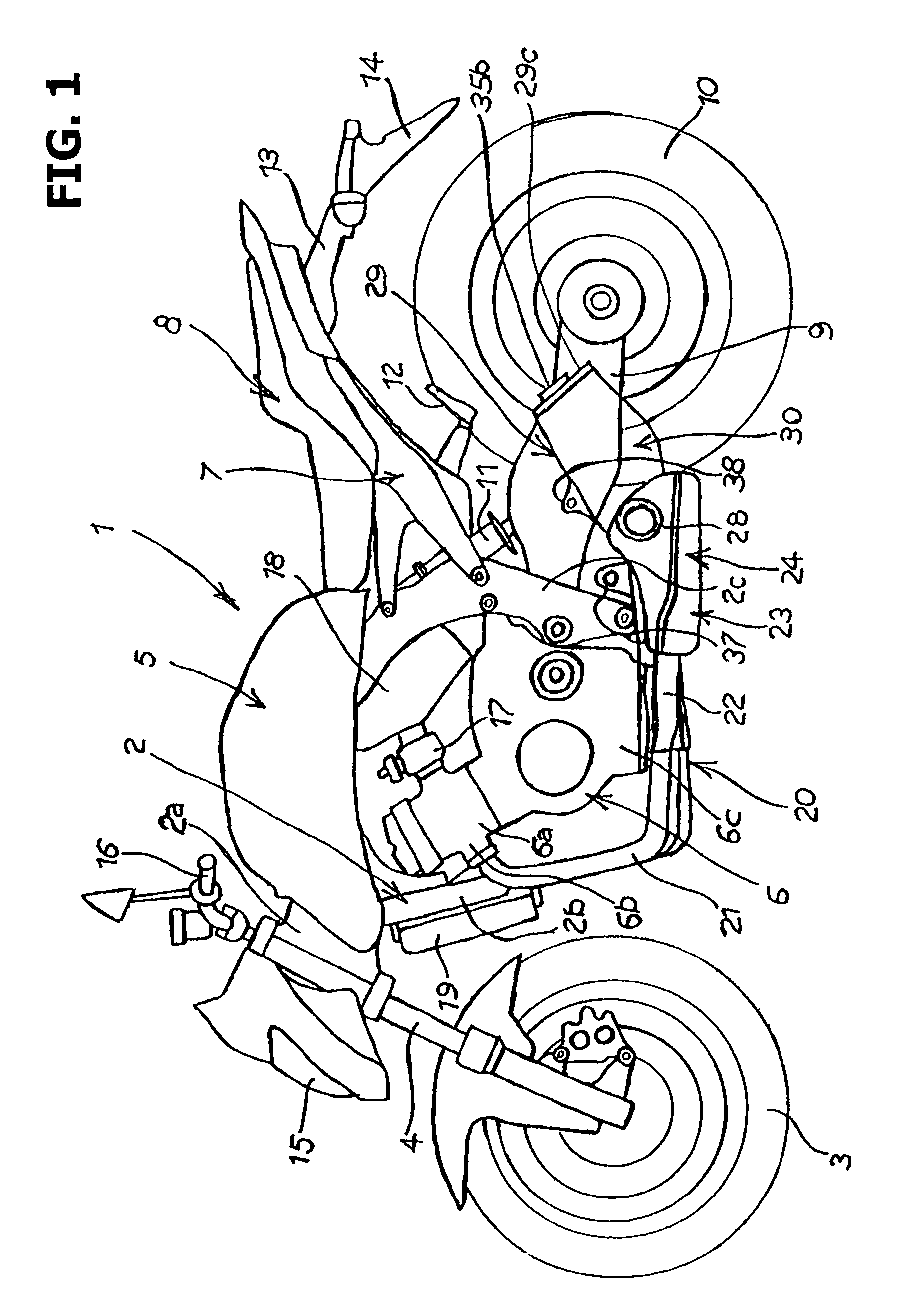
[0032]FIG. 1 is a schematic side view of a motorcycle 1 having an exhaust system 20 according to the present invention.

[0033]In the motorcycle 1, a front wheel 3 is steerably supported by a front fork 4 on the downside of a head pipe 2a at a front end of a frame 2, a fuel t...


PUM


Abstract

An exhaust system for a motorcycle includes exhaust pipes extending from exhaust ports of an engine, a first muffler chamber for receiving the exhaust pipes, a second muffler chamber arranged parallel to and operatively connected with the first muffler chamber, and a silencer disposed in the second muffler chamber. The exhaust system is distributively arranged in a vehicle width direction such that the first muffler chamber is situated on a left side of a center line of the motorcycle defined along longitudinal direction of the motorcycle, and the second muffler chamber is situated on a right side of the center line. The first and second muffler chambers are disposed at a position below the engine. The exhaust gas from the engine is emitted outside the engine via, in sequence, the exhaust pipes, the first and second muffler chambers and the silencer.

Description

CROSS-REFERENCE TO RELATED APPLICATIONS[0001]The present application claims priority under 35 USC §119 based on Japanese patent application No. 2007-286184, filed on Nov. 2, 2007. The entire subject matter of this priority document is incorporated by reference herein.BACKGROUND OF THE INVENTION[0002]1. Field of the Invention[0003]The present invention relates to an exhaust system for a motorcycle, and to a motorcycle incorporating same. More particularly, the present invention relates to a distributive arrangement of components of the exhaust system in a motorcycle.[0004]2. Description of the Background Art[0005]There are several known exhaust systems for a motorcycle. The exhaust systems emit exhaust gas from an engine into the air via an exhaust pipe and a silencer. The engine is generally arranged between front and rear wheels of the motorcycle.[0006]An example of such known exhaust system for a motorcycle is disclosed in the Japanese Patent document JP-A No. 2007-91180, in which...

Claims


Application Information

Patent Timeline
Patent Type & Authority Patents(United States)
IPC IPC(8): B60K13/04B62M7/02F01N1/00F01N1/08F01N3/24F01N13/08
CPCF01N1/084F01N1/086F01N1/089F01N13/02F01N2230/04F01N2470/16F01N2490/04F01N2490/06F01N2590/04
Inventor NISHIJIMA, TOMOKI
Owner HONDA MOTOR CO LTD
Why Eureka
Try Eureka