Flow controller and test method therefor, and flow control method

a flow controller and flow control technology, applied in process and machine control, semiconductor/solid-state device testing/measurement, instruments, etc., can solve problems such as equipment aging, equipment aging also refers to the degradation of performance or characteristics of the members themselves, and equipment aging can be caused

Active Publication Date: 2011-10-11
HITACHI METALS LTD
View PDF6 Cites 12 Cited by
  • Summary
  • Abstract
  • Description
  • Claims
  • Application Information

AI Technical Summary

Benefits of technology

[0059]As can be seen from above, the invention is characterized by determining whether there has occurred a non-negligible deviation in flow control, based on actual data on flow control that has been collected for several days or several weeks. This makes it possible to provide the flow controller which has been improved in keeping track of degradation in accuracy of flow control resulting from the equipment aging, thereby rendering it possible to take action as appropriate against the degradation in accuracy.
[0061](3) The present invention allows, after executing the flow rate test means, delivering the valve drive control information to the flow control valve mechanism 7. The valve drive control information is intended to automatically correct the flow rate through a fluid path 4 or to correct the flow rate based on the result of processing the inquiry on the flow rate correction permission issued to the external system 9. This makes it possible to provide the flow controller which can correct the flow rate through the fluid path 4 to the flow rate set value (R0) immediately after there has occurred a non-negligible deviation from the flow rate set value (R0).

Problems solved by technology

Accordingly, those semiconductor integrated circuits would likely degrade in quality unless precise and high-speed control is performed on the flow rate of a process gas supplied to the semiconductor manufacturing apparatus such as a CVD apparatus.
The equipment aging also refers to degradation in performance or characteristics of the members themselves over time from the start of operation of the manufacturing line.
More specifically, the equipment aging can be caused, for example, by adhesion of chemical products to the inside of a pipeline through which the process gas is supplied, by adhesion of chemical products to sensor pipes or bypass pipes constituting the flow rate sensor, or by degradation in performance of an actuator installed in the flow control valve mechanism.
Once such equipment aging occurs, there would likely occur a slight difference in the valve opening with respect to the one initially available.
However, to perform this testing operation, it was inevitable to stop the operation of the semiconductor manufacturing apparatus.
In other words, this test operation could not be performed while the semiconductor manufacturing apparatus, for example, a CVD apparatus was being used for deposition on wafers.

Method used


Image

  • Flow controller and test method therefor, and flow control method
  • Flow controller and test method therefor, and flow control method
  • Flow controller and test method therefor, and flow control method

Examples


first embodiment

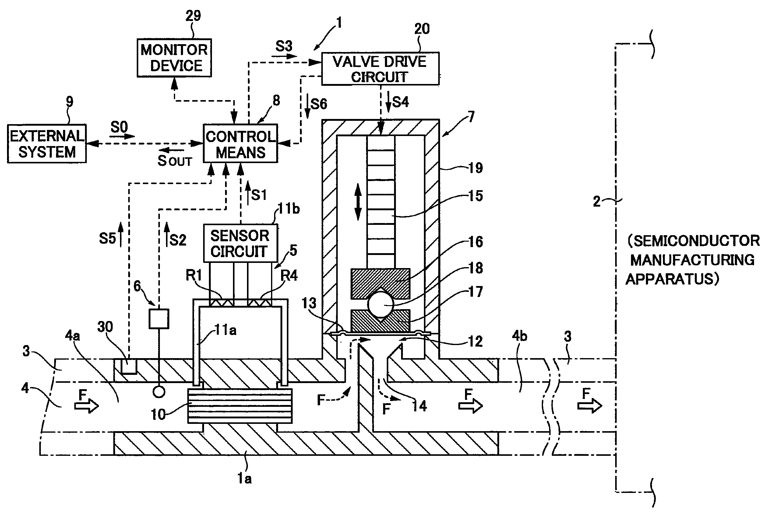
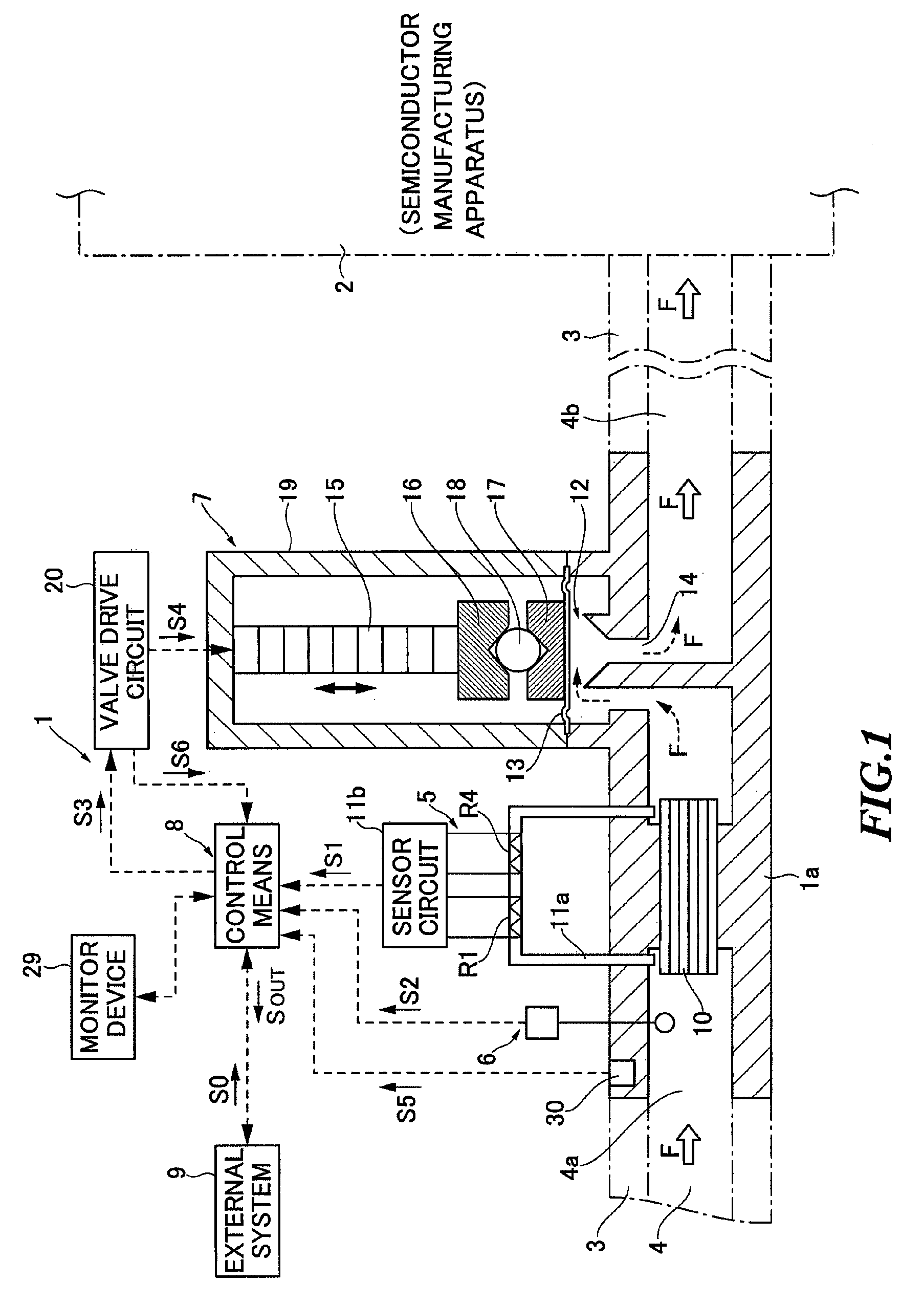
[0165]Now, with reference to the flowcharts shown in FIG. 9 to FIG. 11, a description will be given to the procedure in which the control means 8 of the flow controller 1 tests the accuracy of flow rate control while at the same time providing the flow rate control of the fluid passing through the fluid path 4 using the aforementioned control programs.

[0166]FIG. 9 shows a flowchart in which the main control program Pm of the control means 8 receives from the external system 9 the flow rate set value (R0) carried on the flow rate setting signal S0 by communication interrupt, and then determines the type of the received flow rate set value (R0). FIGS. 10 and 11 each show a flowchart of the procedure in which the main control program Pm tests the accuracy of flow control while providing control to the flow rate through the fluid path 4 based on the flow rate set value (R0) received from the external system 9.

[0167]In the following descriptions, it is described by way of example that t...

second embodiment

[0273]A description will now be made to the present invention. The second embodiment features the means provided to correct the flow rate through the fluid path 4 based on the flow rate test results provided according to the first embodiment described above. That is, the flow controller 1 of the second embodiment features the means provided to correct the valve drive control information (V1) delivered to the laminated piezoelectric device 15 based on the flow rate test information computed by the flow rate test program P11.

[0274]FIG. 12 shows the procedure for flow rate control according to the second embodiment. The difference between the procedure according to the first embodiment shown in FIGS. 10 and 11 and that of the second embodiment lies in step S16 of the first embodiment shown in FIG. 10 (or step S16a of the second embodiment). Note that the contents of each step shown in FIG. 11 of the first embodiment are the same as those of the second embodiment. Furthermore, in FIGS. ...

third embodiment

[0286]To implement the third embodiment, it is necessary to alter the procedure for communicating with the external system 9 shown in FIG. 9 and part of the contents of processing shown in FIG. 10 (or FIG. 12) and FIG. 11. Now, these altered contents of processing will be described below.

[0287]FIG. 13 shows an example of reception processing performed when the flow controller 1 receives a control command or the like from the external system 9 to implement the third embodiment. In FIG. 13, the same processes as those of FIG. 9 are given the same step numbers, whereas newly added steps are provided with step numbers from step S1a to step S1f. Now, to implement the third embodiment, the contents of processing in the newly added steps S1a to S1f will be described.

[0288](Step S1a)

[0289]When a control command is received from the external system, the type of the control command is determined. Then, if the control command is determined to be a flow rate setting signal, then the process pro...


PUM


Abstract

A flow controller and a test method therefor are provided which enable testing of the flow control of a process gas passing through a fluid path during operation of semiconductor manufacturing apparatuses. While the flow control is being performed to adjust the flow rate through the fluid path to a flow rate set value, a predetermined number of pieces of test sampling information is collected and associated with the flow rate set value for storage. The test sampling information is made up of a detected flow rate value of the process gas, a detected pressure value, and valve drive control information delivered to a flow control valve mechanism. Then, coefficients of association are sequentially determined which indicate the associations of the predetermined number of detected flow rate values and pieces of valve drive control information, which are stored as the test sampling information. When the value of a coefficient of association is out of the range of predetermined threshold values, a difference is determined between the valve drive control information made available based on a newly received detected flow rate value and the reference valve drive control information obtained with reference to a valve property information table pre-registered for testing. This difference is employed as test information.

Description

BACKGROUND OF THE INVENTION[0001]The present invention relates to a flow controller for controlling comparatively low flow rates of a fluid passing through fluid paths such as pipelines, a method for testing the accuracy of the flow control provided by the flow controller to control the flow rate through the fluid path, and a flow control method.[0002]Various types of semiconductor products or electronic components are manufactured, for example, by placing wafers in a chamber of a CVD (Chemical Vapor Deposition) apparatus and then supplying into this chamber a process gas that contains raw materials and chemically reactive substances necessary for deposition, thereby fabricating semiconductor integrated circuits on the surface of the wafers. The raw material gas used includes, for example, SiH4, WF6, and NH3. In addition, etching gases for use in etching after deposition include, for example, CH4 or Cl2.[0003]Recently, there has been increasing demand for further reduction in size a...

Claims


Application Information

Patent Timeline
Patent Type & Authority Patents(United States)
IPC IPC(8): G05D7/00G05D11/00G01F1/12G05D7/03
CPCG05D7/0635Y10T137/0324H01L21/205H01L21/02H01L22/00
Inventor GOTOH, TAKAO
Owner HITACHI METALS LTD
Why Eureka
Try Eureka