Bearing for variable pitch stator vane

a stator vane and variable-pitch technology, applied in the direction of bearing unit rigid support, machines/engines, liquid fuel engines, etc., can solve the problems of uneven wear of prior art, detrimental to the correct operation of the variable-pitch device, etc., to reduce component wear and increase the effective area , the effect of discharging vibration energy

Active Publication Date: 2011-10-18
SN DETUDE & DE CONSTR DE MOTEURS DAVIATION S N E C M A
View PDF13 Cites 12 Cited by
  • Summary
  • Abstract
  • Description
  • Claims
  • Application Information

AI Technical Summary

Benefits of technology

[0009]By virtue of this design, the bearing operates like a ball joint and makes it possible to increase the effective area between the pivot and the outer bushing. Component wear is thereby reduced.
[0010]The bushing structure according to the invention also has the advantage that it can, if necessary, have a damping effect. It is able to dissipate vibrational energy when the stator is subjected to aerodynamic excitation. The vibration modes of the stators are thereby attenuated.
[0011]Advantageously, the inner bushing is subdivided into two cylindrical elements at least in the continuation of one another. That allows the inner bushing to adapt to deformations of the pivot. It is possible to increase the number of elements of which the inner bushing is made in order to achieve the best possible compliance.
[0012]More specifically, the various elements are separated by an annular layer of elastomer so as to improve sealing along the pivot.

Problems solved by technology

However, because of the transverse forces and the flexing of the stators, the bushings of the prior art are found to exhibit uneven wear.
Such wear is detrimental to the correct operation of the variable pitch device.

Method used


Image

  • Bearing for variable pitch stator vane
  • Bearing for variable pitch stator vane
  • Bearing for variable pitch stator vane

Examples


Embodiment Construction

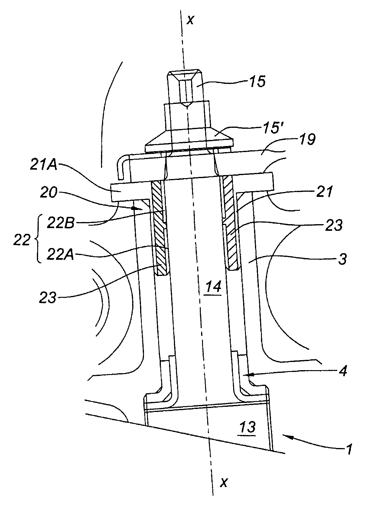
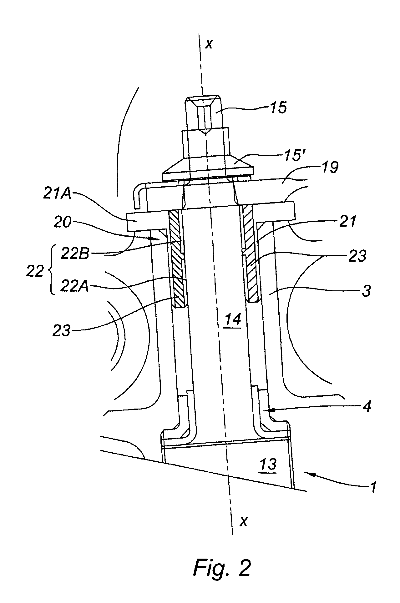
[0018]FIG. 2 shows the pivot 14 of the vane 1 mounted in the bore of the casing 3 in such a way as to allow it to rotate about the axis XX. The pivot ends in a journal 15 to which a nut 15′ secures a rod 19 for rotating the vane about the axis XX.

[0019]The pivot is supported by a bearing 4 at the platform 13 end (the airfoil is not depicted) and by a bearing 20 at the rod 19 end. The invention relates to the bearing 20. This is made up of an outer bushing 21 shrunk into the bore of the casing 3. This outer bushing is therefore cylindrical with a transverse flange 21A, resting on the exterior edge of the bore. This flange is inserted between the casing and the rod 19.

[0020]An inner bushing 22, made of two cylindrical elements 22A and 22B spaced slightly axially apart from one another, is shrunk onto the pivot 14. This inner bushing extends axially over the same length as the outer bushing 21.

[0021]A space is formed between the two bushings and this space is occupied by an elastomeric...


PUM

PropertyMeasurementUnit
outer diametersaaaaaaaaaa
inner diameteraaaaaaaaaa
relative movementsaaaaaaaaaa

Abstract

A bearing for a turbomachine variable pitch stator vane pivot mounted in a bore of the turbomachine casing is disclosed. The bearing includes an inner bushing secured to the pivot and an outer bushing secured to the bore. An elastomeric material is inserted between the inner bushing and the outer bushing to allow the vane to pivot about its axis and absorb at least some of the flexing of the pivot at right angles to the axis. The design makes it possible to reduce bearing bushing wear.

Description

BACKGROUND OF THE INVENTION AND DESCRIPTION OF THE PRIOR ART[0001]The present invention relates to the field of turbomachines such as gas turbine engine axial compressors and is aimed in particular at the machine's variable pitch stator vanes.[0002]An articulated system, such as the variable pitch stator vanes of a gas turbine engine compressor, comprises parts which move relative to one another. FIG. 1 schematically depicts a variable pitch stator vane 1 mounted in the machine casing 3. The stator vane comprises an airfoil 12, a mounting plate or platform 13 and a pin forming a pivot 14 at one end. The pivot 14 is housed in a radial orifice or bore formed in the wall of the casing 3 via various bearings. The vane is held only at this end. The other end holds a floating annular element 16 in which it is pivotably mounted via a second pivot 17. The annulus is provided with sealing means to seal against the part of the rotor 18 adjacent to it.[0003]The pivot 14 swivels in the correspo...

Claims


Application Information

Patent Timeline
Patent Type & Authority Patents(United States)
IPC IPC(8): F01B25/02
CPCF01D17/162F04D29/057F16F1/3863F04D29/563F05D2300/431F05D2300/501
Inventor HOURADOU, EMMANUELHULIN, HERVEJUSTE, SEBASTIENRAULIN, DOMINIQUE
Owner SN DETUDE & DE CONSTR DE MOTEURS DAVIATION S N E C M A
Why Eureka
Try Eureka